Tilting of Rigid Bodies
Neil Trivedi
Teacher

Tilting of Rigid Bodies
Tilting occurs when a rigid body, such as a beam or rod resting on two supports, is about to lose contact with one of its supports. As the load on one side increases, the reaction force at the other support decreases. When that reaction becomes , the body is said to be at the point of tilting.
At this instant, the body is still in equilibrium but is about to rotate about the support that remains in contact. We can find unknown values using the principle of moments and the equilibrium of forces.
General Steps for Solving Tilting Questions
1) Draw or annotate a diagram - Label all the forces acting on the body (e.g. weights, reaction forces etc) and any distances that will be needed when taking moments.
2) Identify the point of tilting - When tilting begins, the body is about to rotate about one support. The reaction force at the other support becomes , and the support that stays in contact with the body acts as the pivot.
3) Take moments about the pivot - Set the sum of clockwise moments to equal the sum of anti-clockwise moments. At this instant, the system is still in horizontal equilibrium, so the resultant moment is .
4) Solve for any unknown values - For example, a question may ask for a distance a load can move before tilting begins, or a mass that causes tilting.
Example 1:
The diagram shows a non-uniform beam with a length of m and a mass of kg. It rests horizontally and in equilibrium on two supports at and , where m and m. The centre of mass of the beam is m from . A box of mass kg is placed at , and another box of mass of kg is placed at . The beam is on the point of tilting about . The beam is modelled as a non-uniform rod, and the boxes are modelled as particles.
Find the value of .
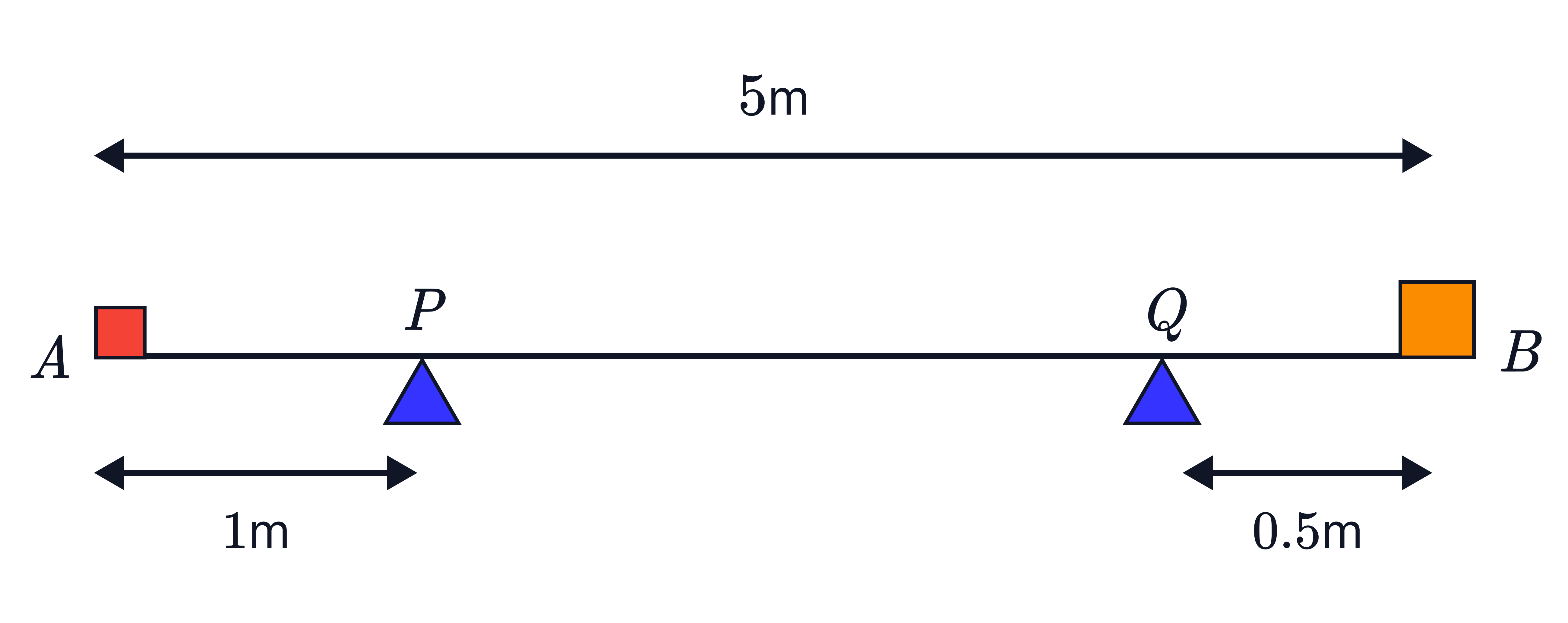
Step 1: Annotate the diagram with the forces and distances.
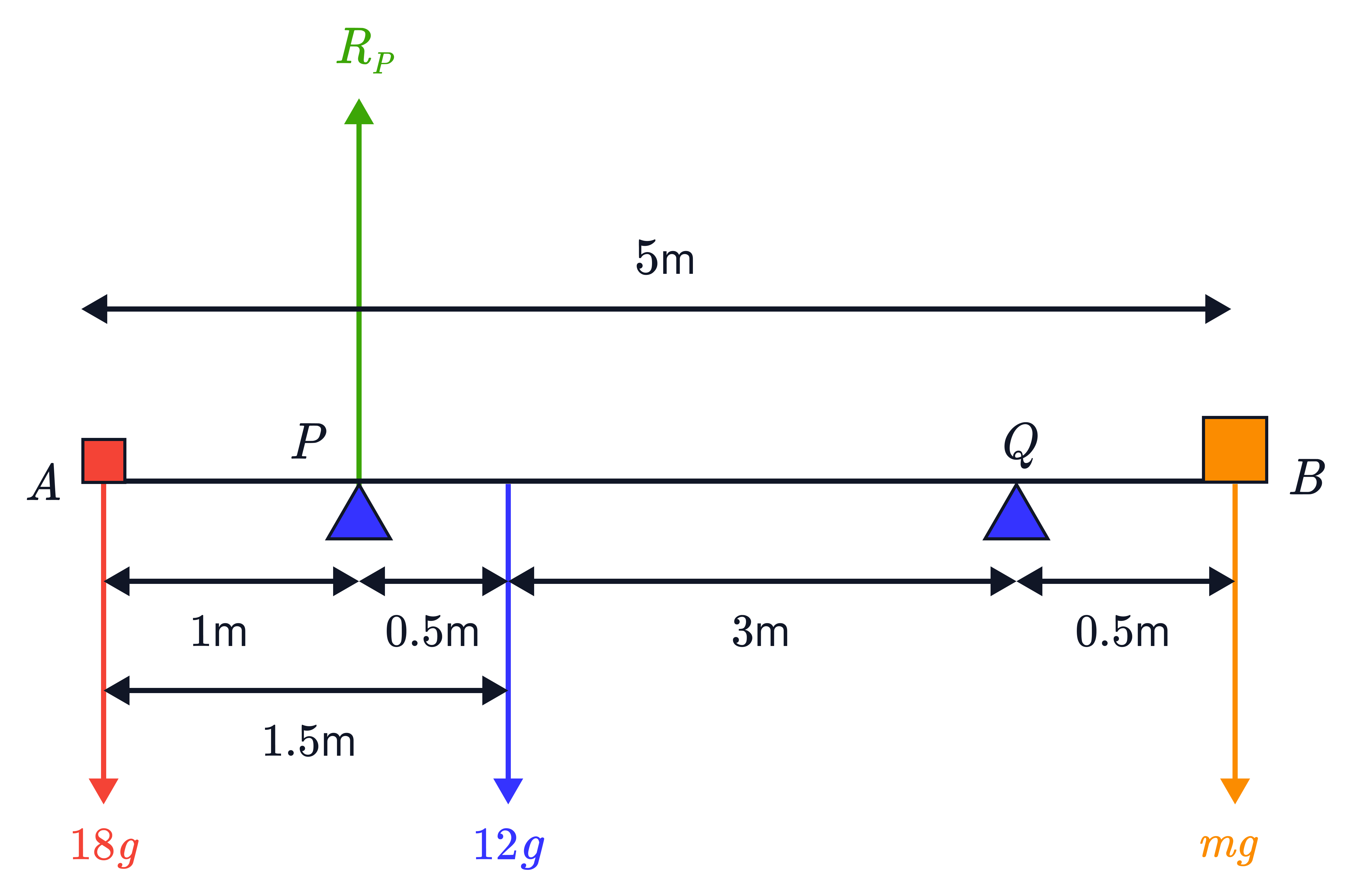
To note:
• The reaction forces exerted on the boxes are excluded because the beam doesn’t experience them, only the weights.
• The question states that the beam is on the point of tilting about . This means that the reaction force at becomes and we can exclude it from our calculation. The beam will, therefore, pivot about , so moments are taken about that point.
Step 2: Take moments about and solve for .
• The force acts at a perpendicular distance of m and would cause the beam to rotate anti-clockwise about .
• The force acts at a perpendicular distance of m and would cause the beam to rotate clockwise about .
• The force acts at a perpendicular distance of m and would cause the beam to rotate clockwise about .
• The force acts at a perpendicular distance of m, so no moments are generated. Therefore, we can exclude this from the calculation.
All of this is illustrated in the diagram below.

Since the beam is in horizontal equilibrium, the resultant moment about is . Therefore, we equate the clockwise moment and anti-clockwise moment about and solve for .
Clockwise moment Anti-clockwise moment
No answer provided.
Example 2:
A beam has a length of m and a mass of kg. The beam is smoothly supported at points and , where m and m, as shown in the diagram. A boy of mass kg stands on the beam at the point , where is the midpoint of . The beam, with the boy standing on it, remains in horizontal equilibrium. The beam is modelled as a uniform rod, and the boy is modelled as a particle.
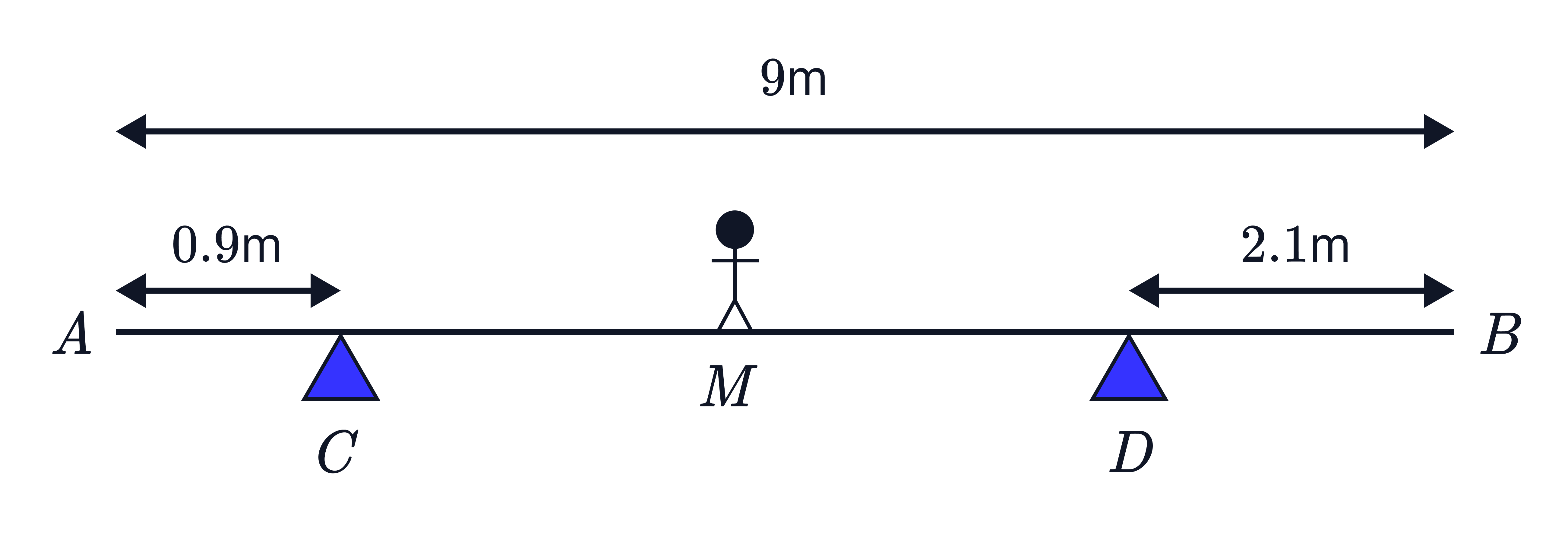
a) Calculate the magnitude of each of the reaction forces acting on the beam at and .
Step 1: Annotate the diagram with all forces and distances.
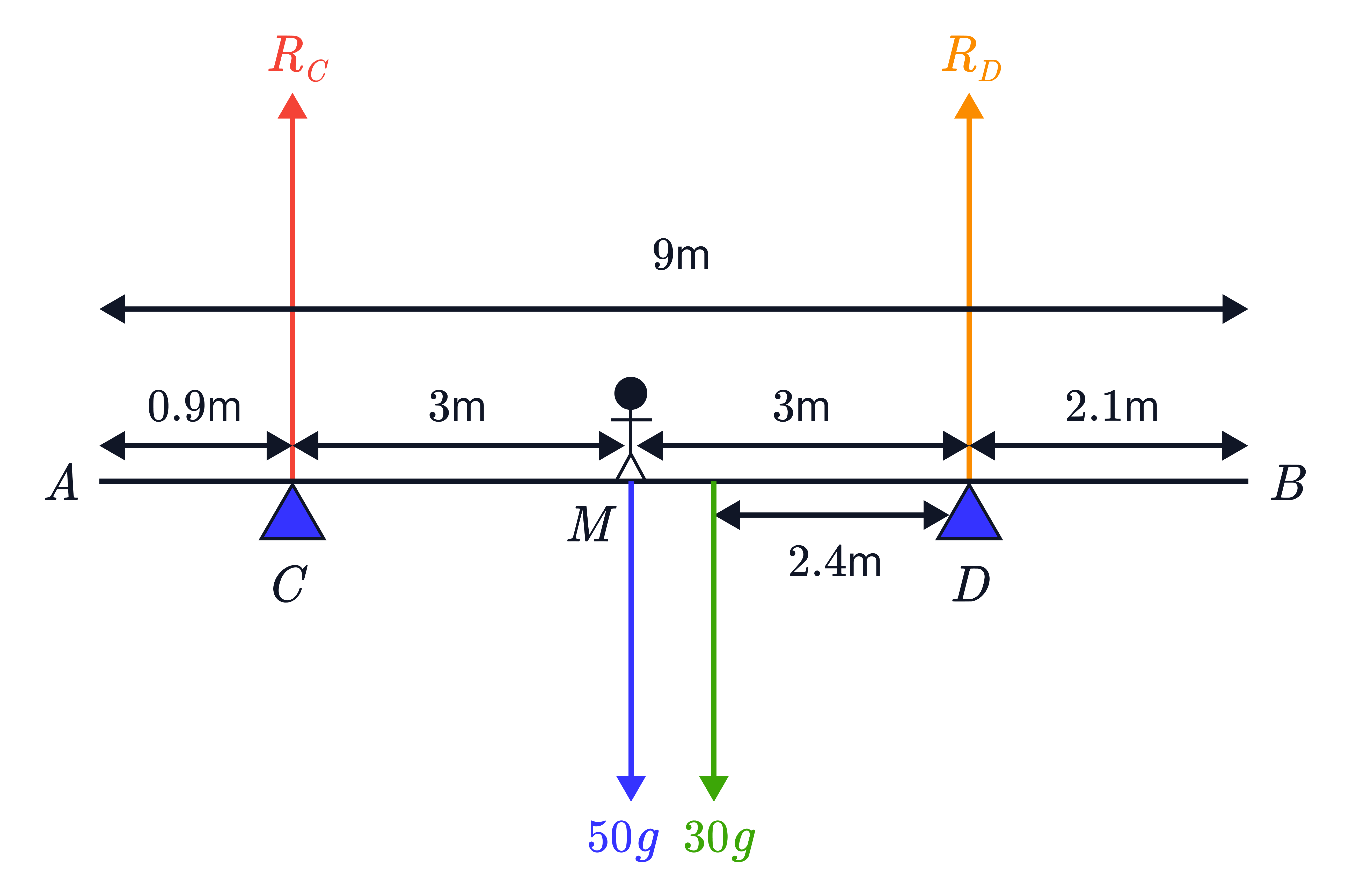
To note:
• The beam is uniform, so its centre of mass acts at the midpoint, m away from each end.
• The reaction force exerted on the boy is excluded because the beam only experiences his weight.
• The reaction forces are different at and so we do not label both of them as .
• Since we have two unknowns, we need two equations which we can form by equating forces and moments and solving simultaneously.
Step 2: Equate the upward and downward forces as the system is in horizontal equilibrium.
Upward forces:
Downward forces:
Now, we take moments about one of the pivots to find one of the reaction forces. Let’s take moments about (though, we could also choose to take moments about ).
Step 2: Take moments about .
• The force acts at a perpendicular distance of m and would cause the beam to rotate clockwise.
• The force acts at a perpendicular distance of m and would cause the beam to rotate anti-clockwise.
• The force acts at a perpendicular distance of m and would cause the beam to rotate anti-clockwise.
• The force acts at a perpendicular distance of m, so no moments are generated. Therefore, we can exclude this from the calculation.
All of this is illustrated in the diagram below.
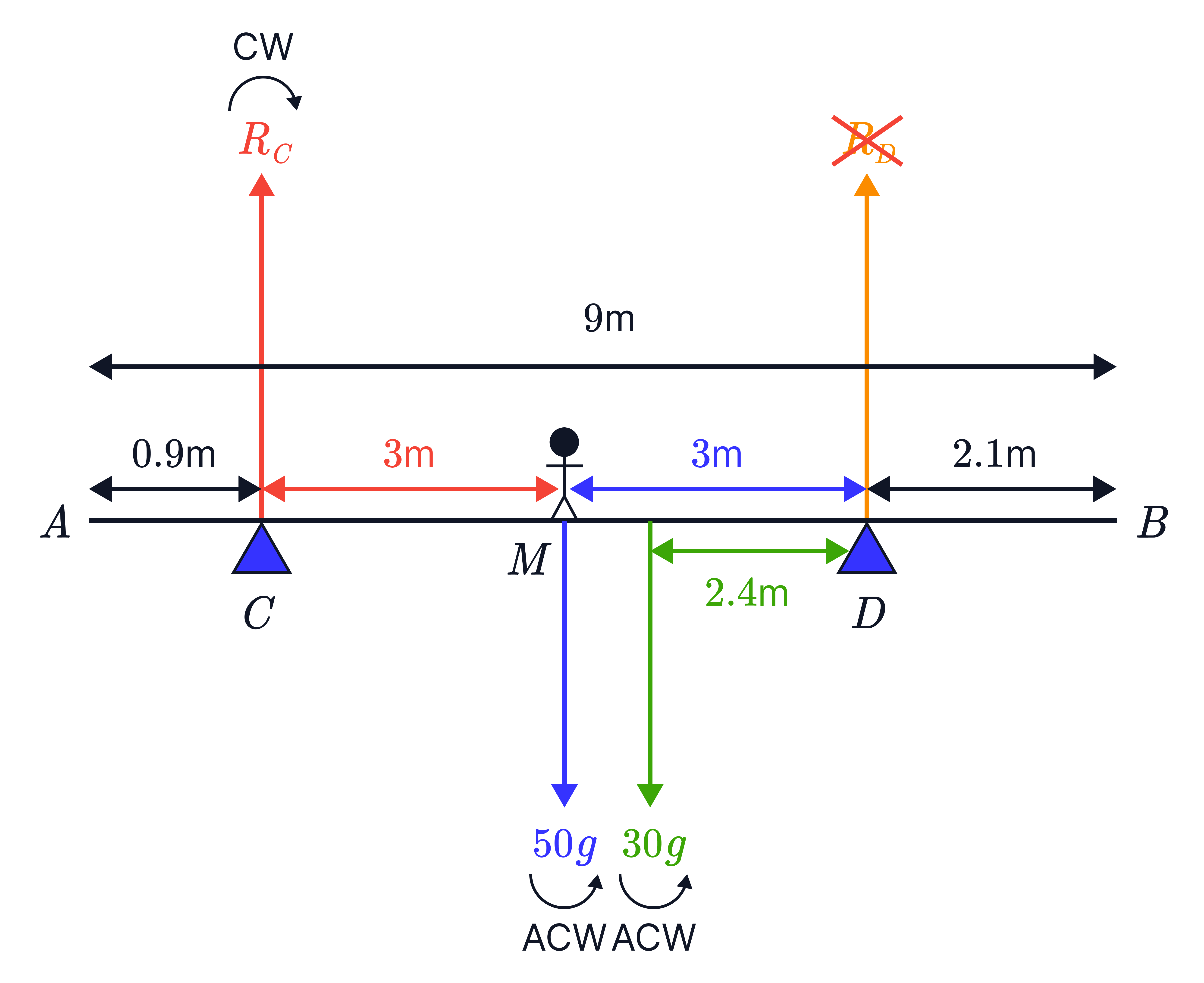
Since the beam is in horizontal equilibrium, the resultant moment about is . Therefore, we equate the clockwise moment and anti-clockwise moment about .
Clockwise moment Anti-clockwise moment
N
Substitute into the equation we obtained in step 2 to get .
N
The boy next moves and stands at a point on the beam, so that the beam is at the point of tilting about .
b) Determine the distance .
• Let the distance be m.
• Since the beam is at the point of tilting about , the reaction force at becomes . Therefore, the boy must have moved to the right of , so acts as the pivot and we take moments about it.
Single Step: Take moments about and solve for .
• The force acts at a perpendicular distance of m and it would cause the beam to rotate clockwise.
• The force acts at a perpendicular distance of m and it would cause the beam to rotate anti-clockwise.
• As mentioned before, we exclude in the calculation because no moments are generated by it.
Here’s a diagram illustrating the new situation.
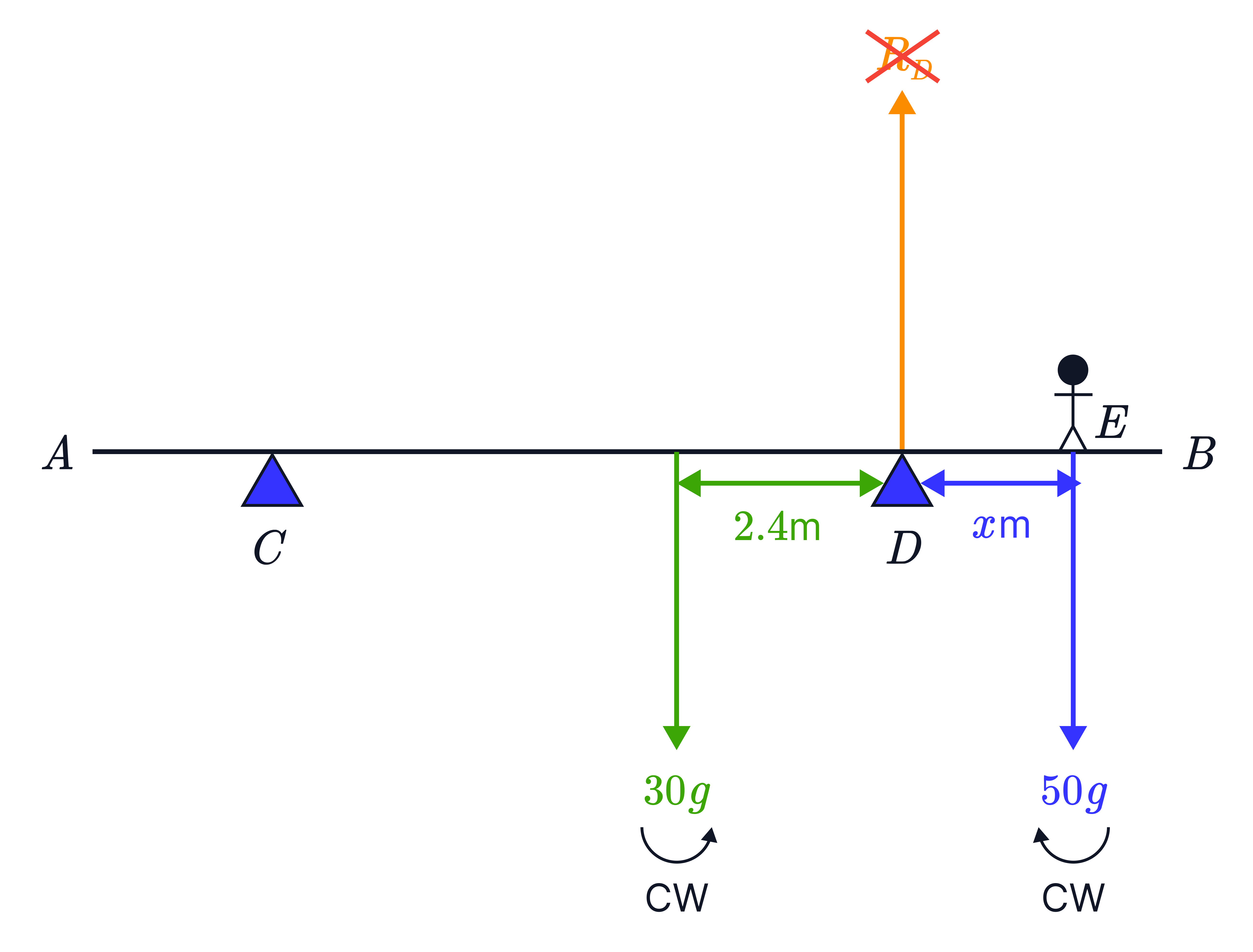
At the point of tilting, the beam is still in horizontal equilibrium, so the resultant moment about is . Therefore, we equate the clockwise and anti-clockwise moments about .
Clockwise moment Anti-Clockwise moment
m
No answer provided.
Challenging Question