Shapes of Simple Molecules & Ions
Lajoy Tucker
Teacher

Contents
Shapes of Simple Molecules
The shape of a simple molecule is determined using valence shell electron pair repulsion (VSEPR) theory. It is based on the key principle that electron pairs repel each other and so position themselves as far from each other as possible.
| Electron Pairs | Electron Geometry | Angle | Example | |
| 2 | Linear | 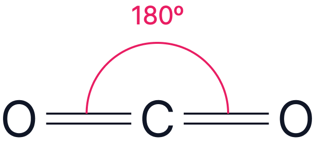 |
||
| 3 | Trigonal Planar | 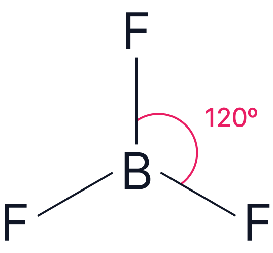 |
||
| 4 | Tetrahedral | 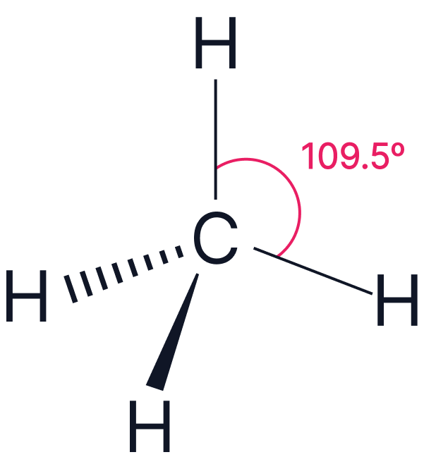 |
||
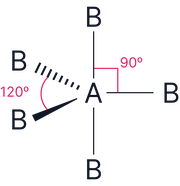
| 5 |
Trigonal Bipyramidal |
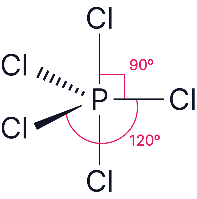 |
||
| 6 | Octahedral | 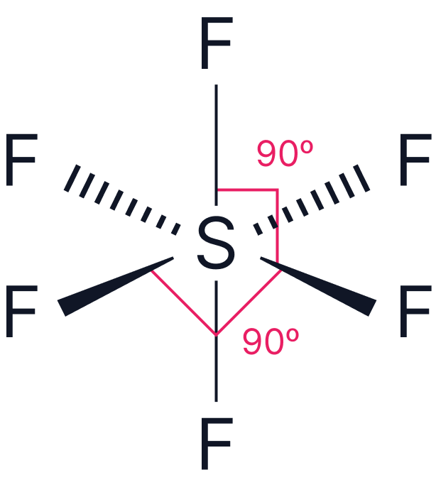 |
Notation
Each line represents a single covalent bond (a shared pair of electrons). To represent the shapes in three dimensions:
Solid lines represent bonds in the plane of the paper
Dashed lines represent bonds going into the page (away from the viewer)
Wedges represent bonds coming out of the page (towards the viewer)
Lone pairs can be represented as two dots and/or a lobe as below.
Lone pairs repel more strongly than bonding pairs.
This affects bond angles:
More lone pairs → smaller bond angles as they reduce bond angles by ~2.5 degrees for each lone pair.
Order of Repulsion:
Lone pair–lone pair > Lone pair–bond pair > Bond pair–bond pair
Example 1
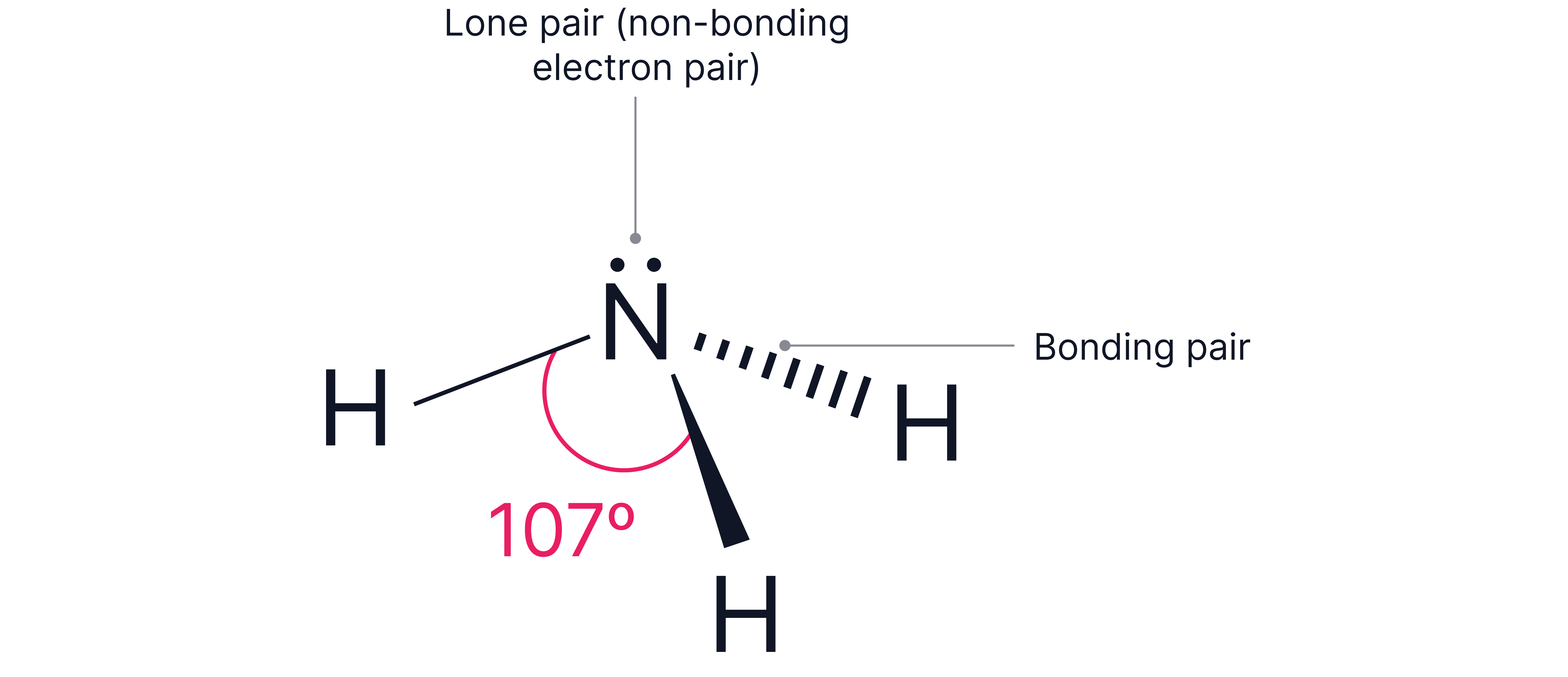
3 bonding pairs and 1 lone pair around the central atom. e.g .
Electron geometry = tetrahedral (4 electron pairs total)
The lone pair reduces the typical tetrahedral bond angles ()by resulting in bond angles of .
No answer provided.
Example 2
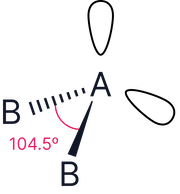
2 bonding pairs and 2 lone pairs around the central atom e.g.,
Electron geometry = tetrahedral (4 electron pairs total)

The lone pairs reduces the typical tetrahedral bond angles () by 2 x resulting in bond angles of .
Due to the increased repulsion of lone pairs, where there is more than one option for their placement, they are positioned such that overall repulsion is reduced.
No answer provided.
Example 3
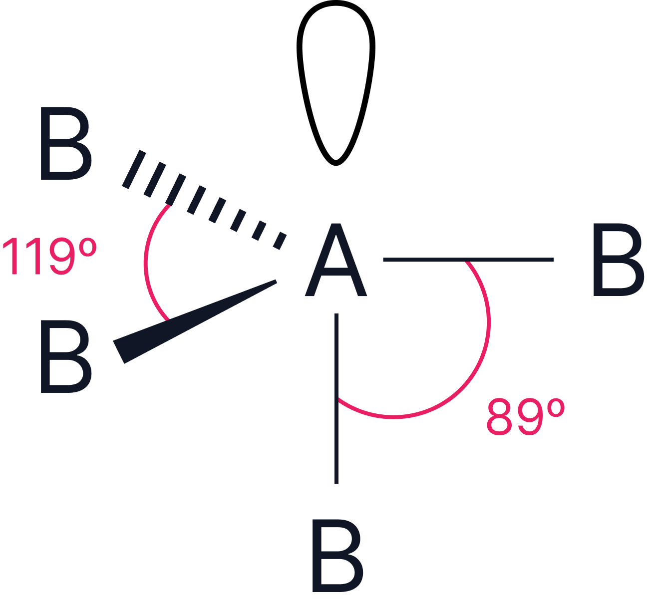
4 bonding pairs, and 1 lone pair surrounding the central atom e.g
Electron geometry = trigonal bipyramidal (5 electron pairs)
The lone pair must be positioned to minimise repulsion and therefore takes an equatorial position where it is from two bonds and from two bonds.
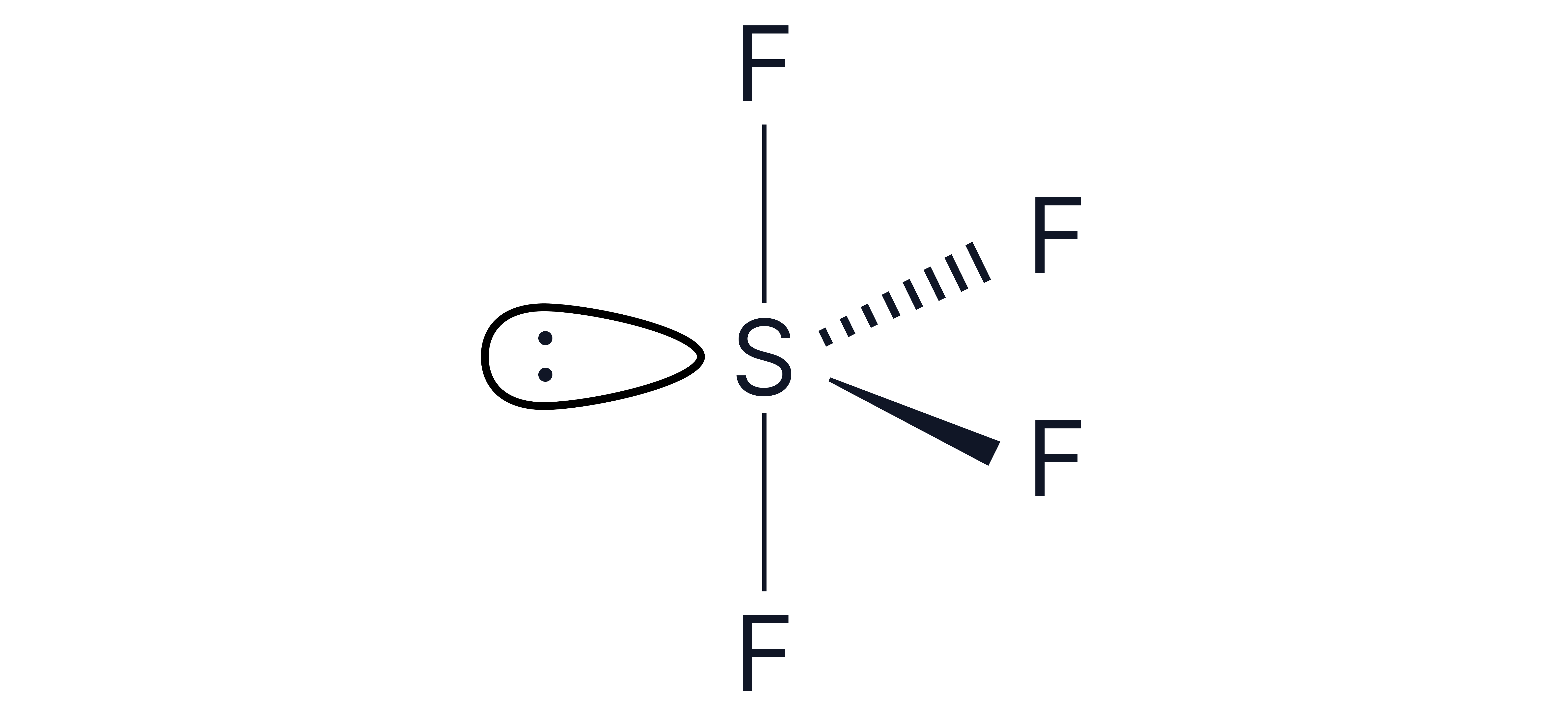
This results in a see-saw shape.
No answer provided.
Example 4
4 bonding pairs, and 2 lone pairs surrounding the central atom e.g.,
Electron geometry = octahedral (6 electron pairs)
The 2 lone pairs must be positioned to minimise repulsion and therefore take the axial positions to be as far from each other as possible.
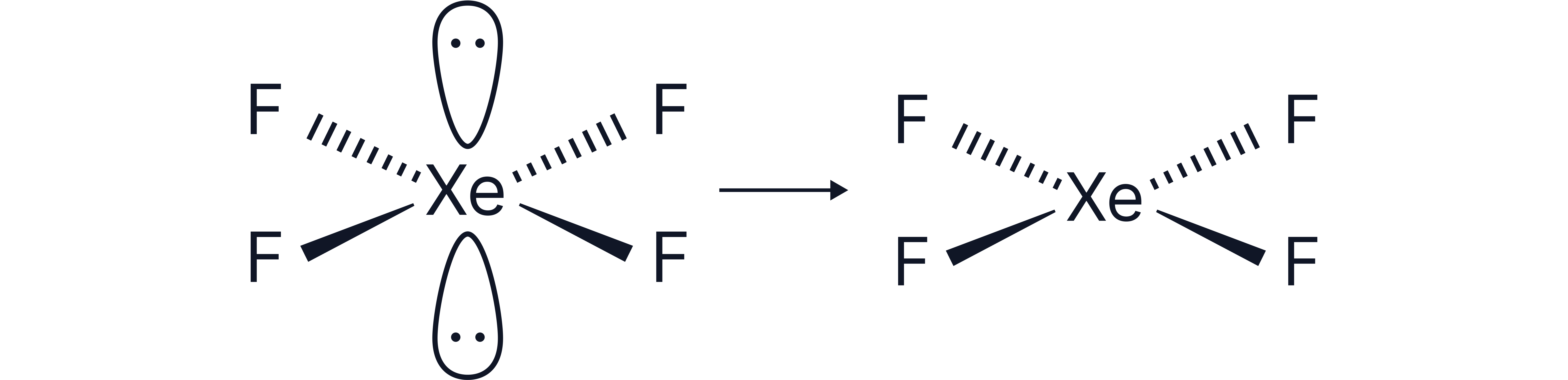
This results in a square planar shape
No answer provided.
Note – the bond angles here do not change as the lone pairs are positioned opposite each other.
No answer provided.
Working Out Electron Pairs
The number of electron pairs around a central atom can be determined using various methods.
This electron counting method works where only single covalent bonds are being formed e.g. bonds with hydrogen atoms or halogens.
Step 1: Count valence electrons on central atom (based on group number)
Step 2: Add the number of bonds being formed
Step 3: Add electrons if there is a negative charge or subtract electrons if there’s a positive charge
Step 4: Divide by 2 to determine total number of electron pairs
Step 5: Deduce number of bonding pairs and lone pairs
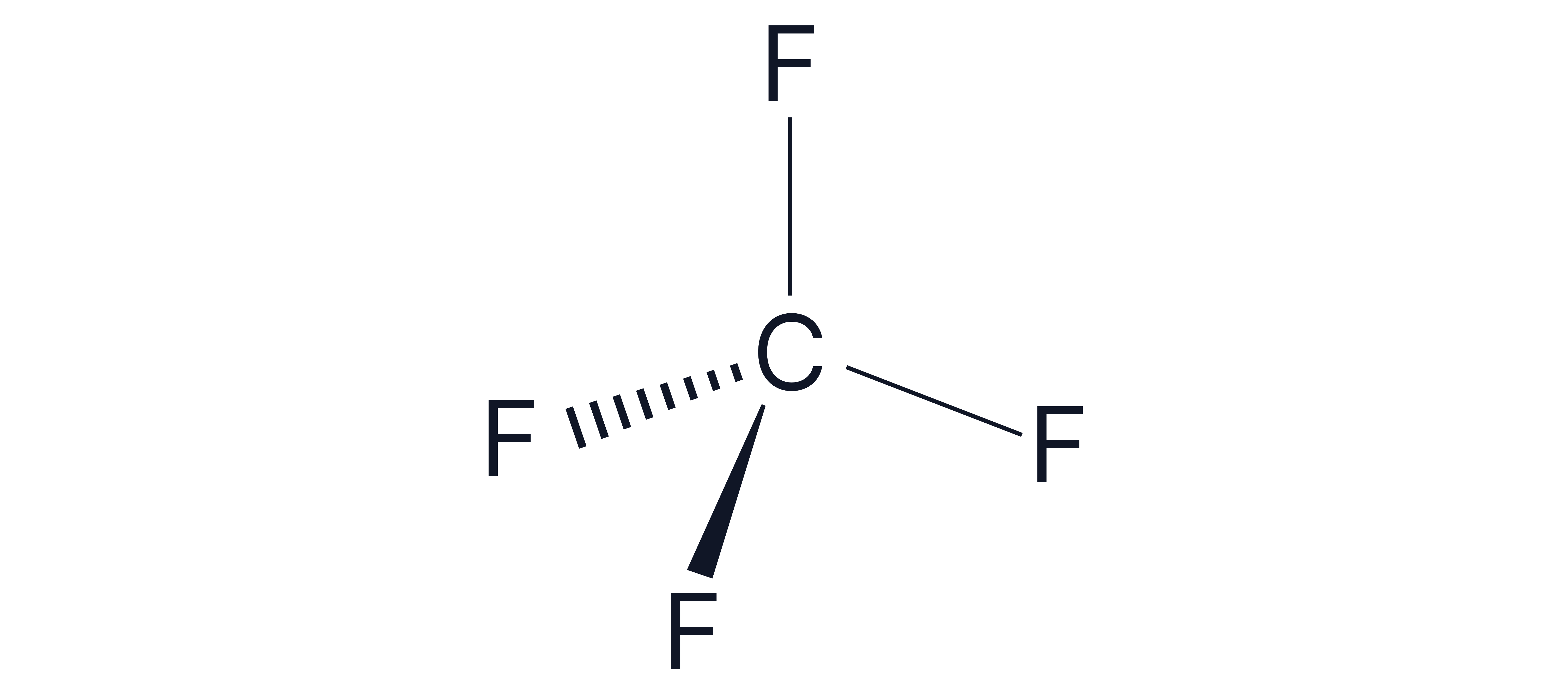
Example 1 -
1. Number of electrons around central carbon atom = 4
2. Add 4 for the number of bonds being formed = 8
3. No charge so skip this step
4. Divide by 2 🡪 8/2 = 4 electron pairs
5. All 4 of the electron pairs are bonding pairs (as there are 4 F’s)
Therefore, 4 bonding pairs and 0 lone pairs
Shape = Tetrahedral
Bond angle =
No answer provided.
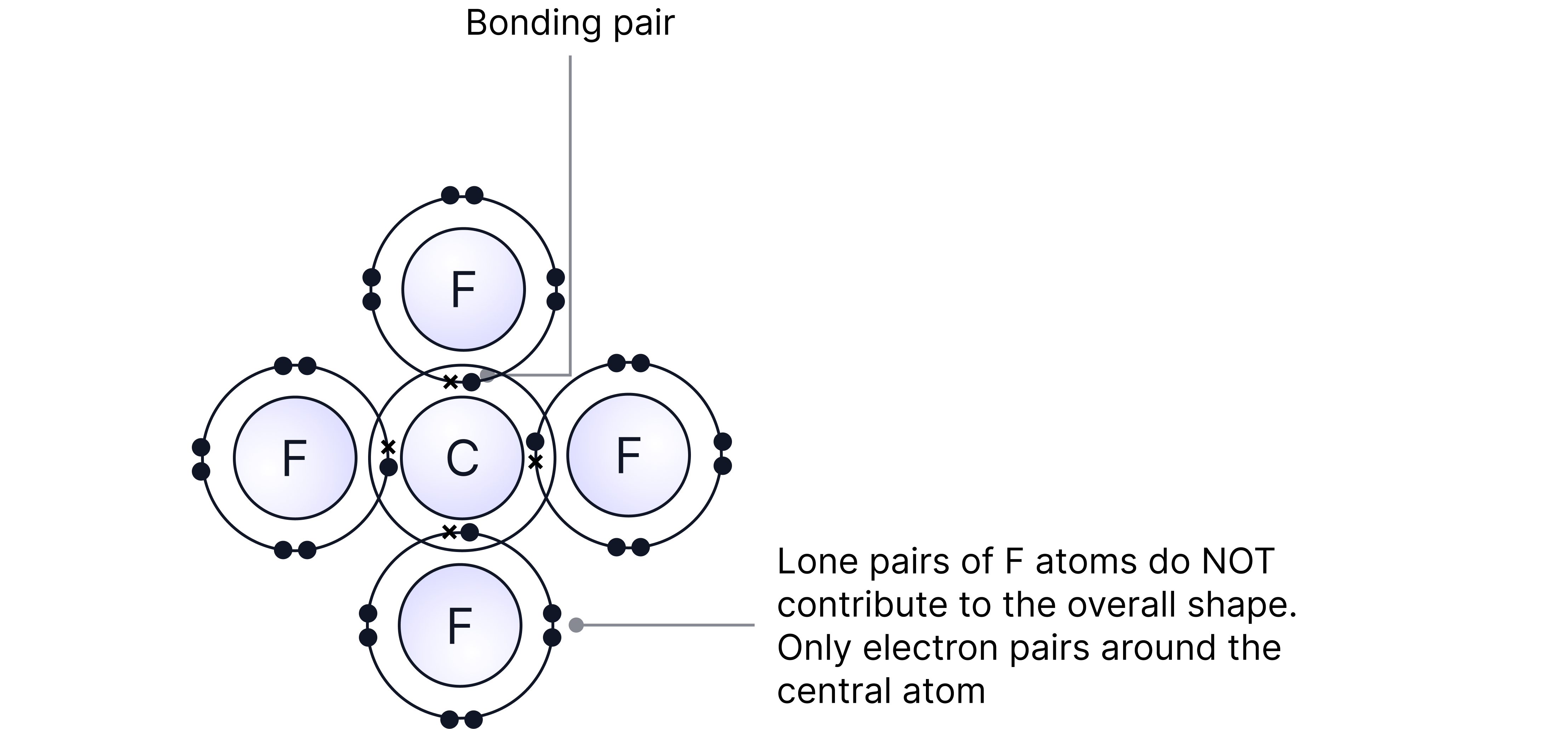
Note – drawing a dot and cross diagram can be used instead and gives the same answer.
No answer provided.
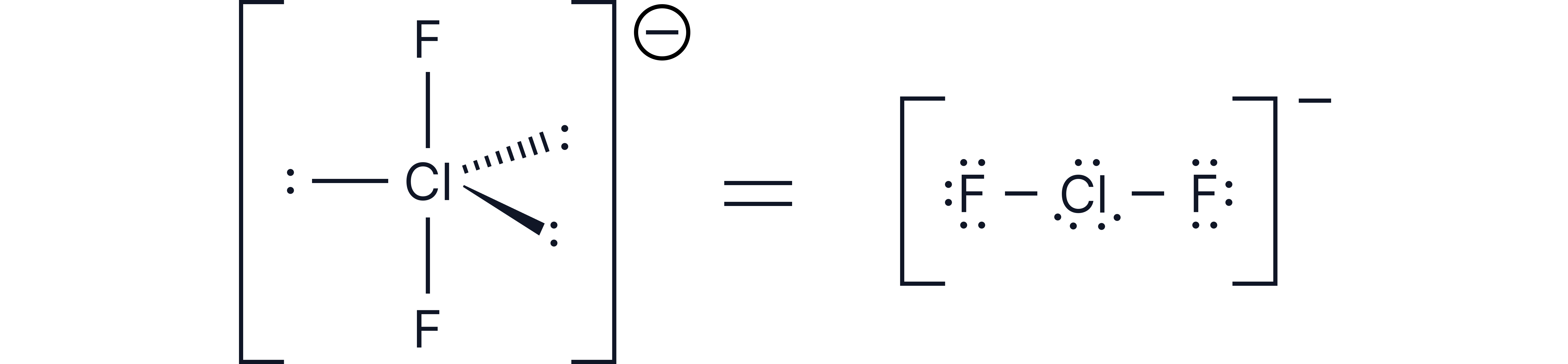
Example 2 -
1. Number of electrons around central chlorine atom = 7
2. Add 2 for the number of bonds being formed = 9
3. Add 1 for the 1- charge = 10
4. Divide by 2 🡪 10/2 = 5 electron pairs
Therefore, 2 bonding pairs and 3 lone pairs
Based on trigonal bipyramidal
3 lone pairs in equatorial positions (around the middle) to minimise repulsion
Shape = Linear
Bond angle =
No answer provided.
Molecules with Double Bonds
Oxygen forms double bonds sharing two pairs of electrons with bonded atoms. As such, the above electron counting method is not suitable.
Constructing dot and cross diagrams is appropriate here to ensure the double bonds are accounted for.
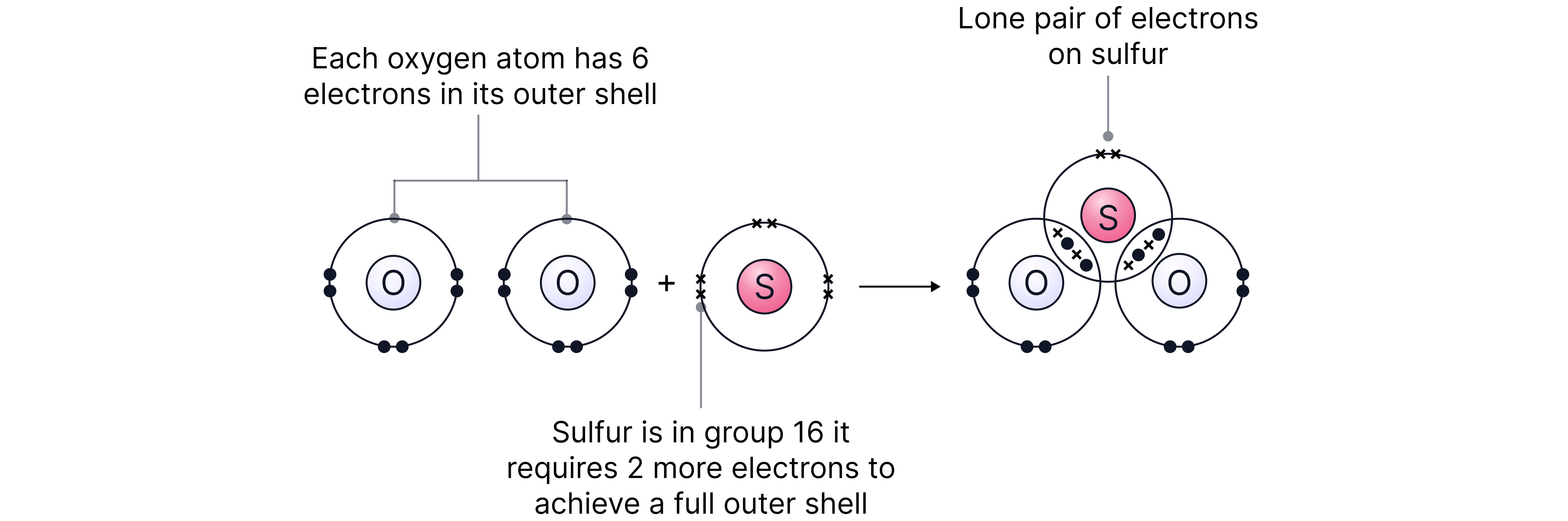
Double bonds here can be treated the same as single bonds when using VSEPR. They can be called bonding ‘regions’ as opposed to bonding pairs.
has 2 bonding regions and 1 lone pair
Shape based on trigonal planar (3 electron pairs)
Shape = Bent
Bond angle = 120-2.5 =
The O=S=O bond angle is actually due to increased repulsion between the double bonds but the general rule of subtracting can be used in an exam context.

Question:
Draw the shape of
1. Number of electrons around central sulfur atom = 6
2. Add 5 for the number of bonds being formed = 11
3. Add 1 for the 1- charge = 12
4. Divide by 2 🡪 12/2 = 6 electron pairs
5. Only 5 of these are bonding pairs (as there are 5 F’s)
Therefore, 5 bonding pairs and 1 lone pair. Based on octahedral shape (6 electron pairs)
Note – as all bond angles in an octahedron are the same, it does not matter where the lone pair is positioned. All positions are the same.
Shape = Square pyramidal

Summary
|
Total number of electron pairs |
Number of bonding pairs |
Number of lone pairs |
Shape |
|
|
2 |
2 |
0 |
 |
Linear |
|
3 |
3 |
0 |
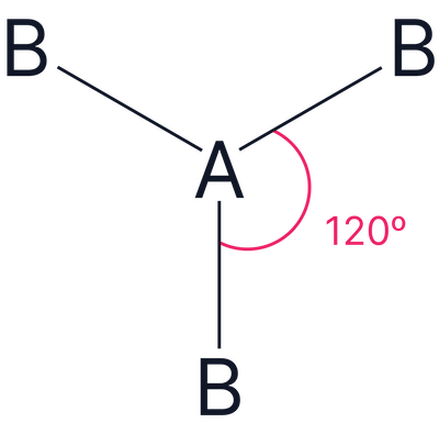 |
Trigonal planar |
|
2 |
1 |
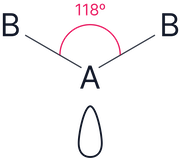 |
Bent (V-shape) |
|
|
4 |
4 |
0 |
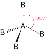 |
Tetrahedral |
|
3 |
1 |
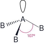 |
Trigonal pyramidal |
|
|
2 |
2 |
 |
Bent (V-shape) |
|
|
5 |
5 |
0 |
 |
Trigonal bipyramidal |
|
4 |
1 |
 or or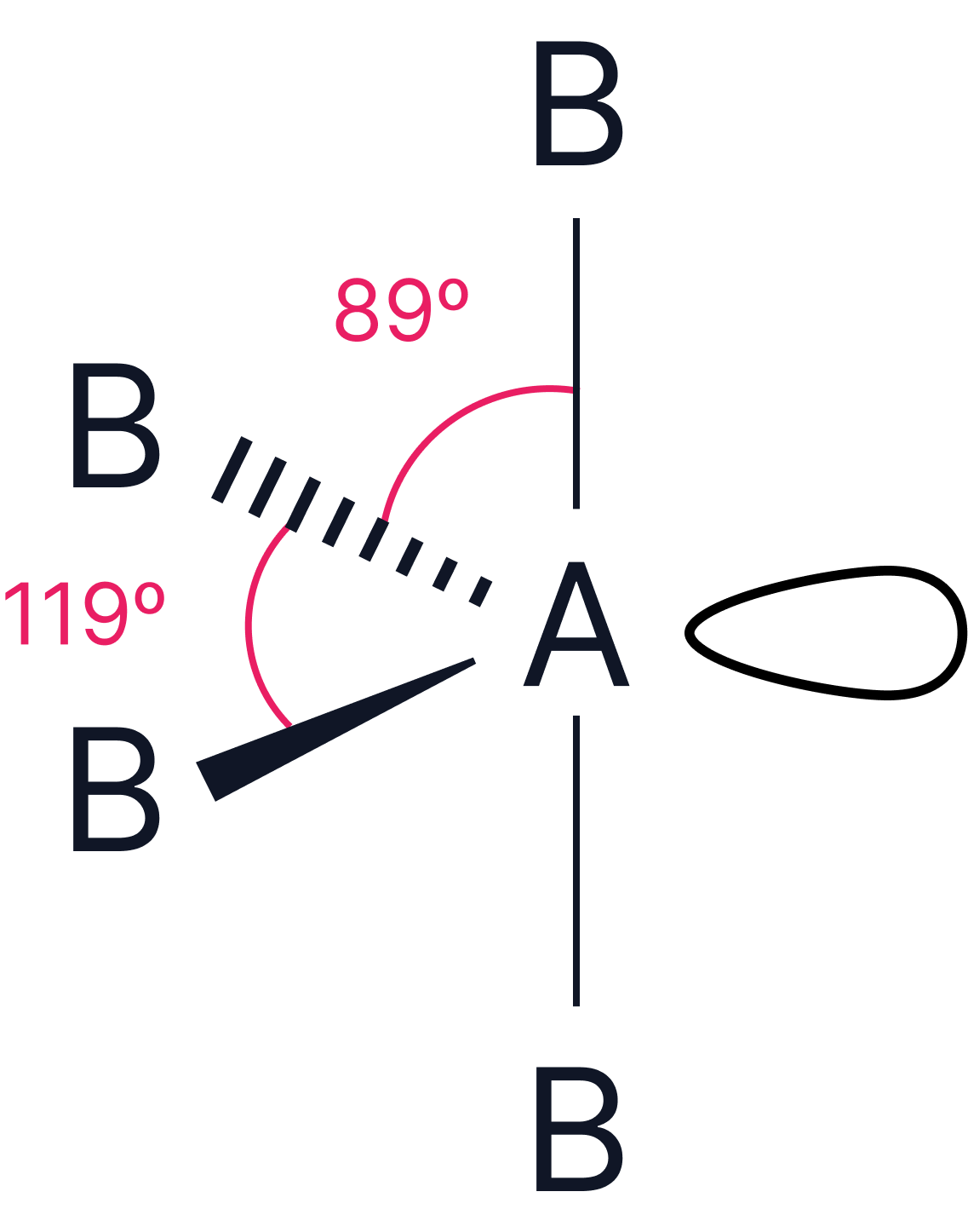 |
Trigonal pyramidal or see-saw |
|
|
3 |
2 |
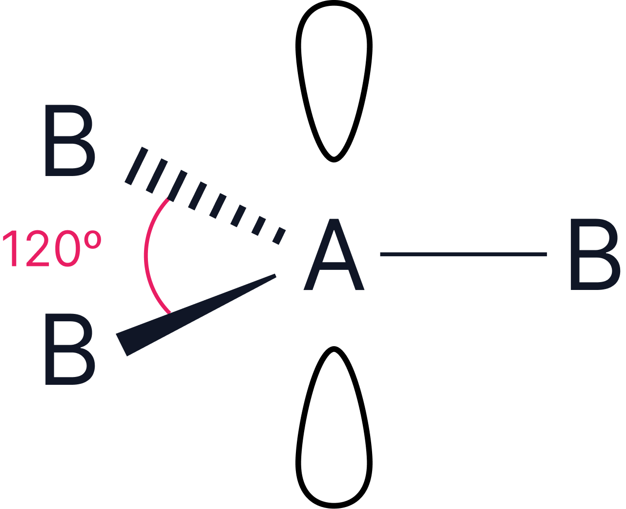 or or 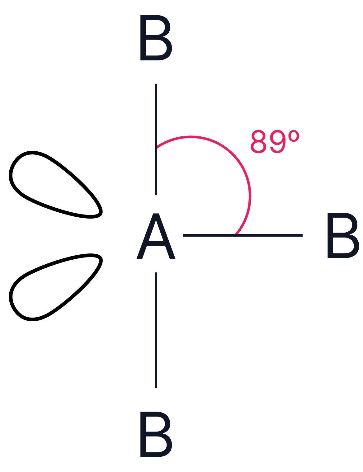 |
Trigonal planar or T-shape |
|
|
6 |
6 |
0 |
 |
Octahedral |
|
5 |
1 |
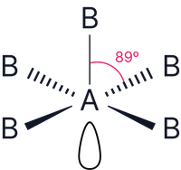 |
Square pyramidal |
|
|
4 |
2 |
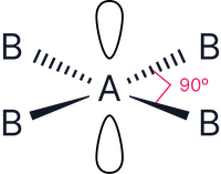 |
Square planar |
|
No answer provided.