Electromagnetic Induction
Brook Edgar
Teacher

Explainer Video
The Generator Effect
Previously, we examined Faraday's law for a magnet moving through a conductor, causing an induced emf. This principle also applies if a conductor is moved through a magnetic field, as the number of field lines cutting the conductor changes.
The magnitude of the induced emf can be increased if we increase the speed of motion, the strength of the magnetic field or the number of turns on the coil of wire. As shown by the equation:
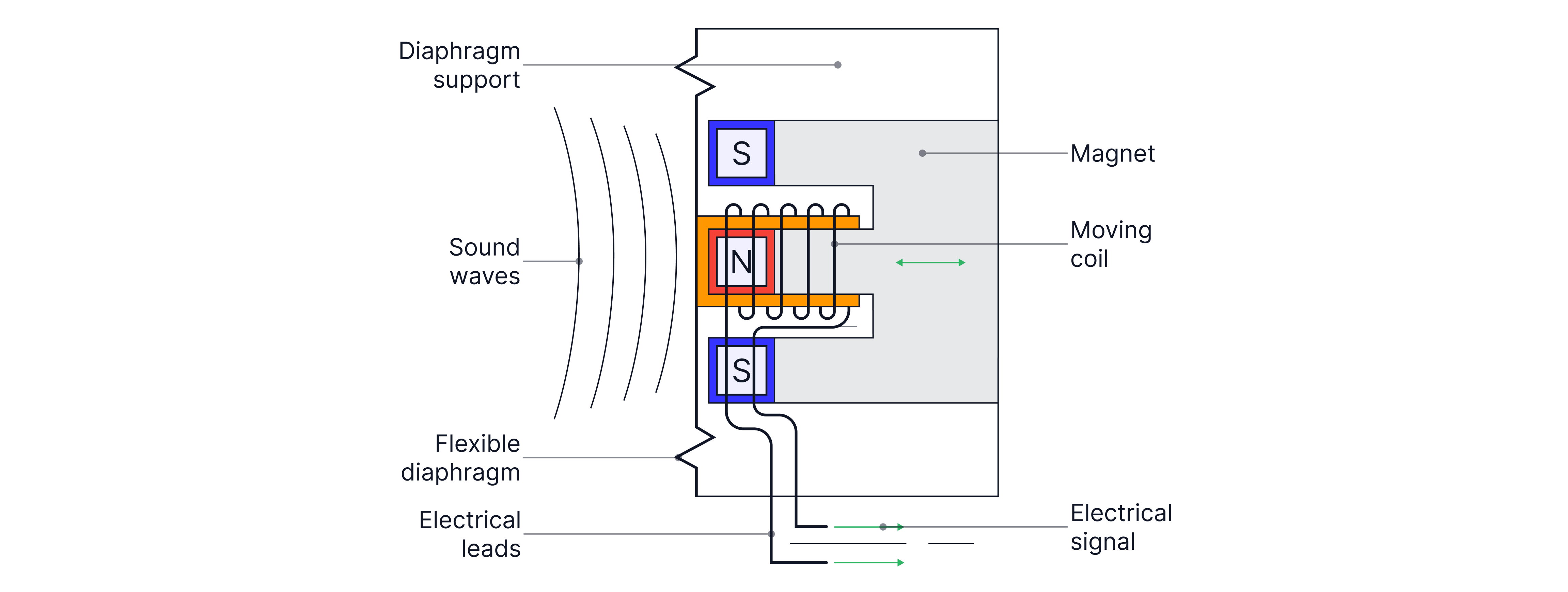
Microphones use the generator effect to convert sound waves into electrical signals. The pressure wave causes the diaphragm in the microphone to vibrate, which causes the coil to vibrate as it is attached to the diaphragm. The moving coil of wire cuts through the magnetic field lines from the permanent magnet inside the microphone, inducing an electromotive force (emf) in the wire due to Faraday's law. The resulting current matches the frequency and amplitude of the original sound wave.
Remember: Faraday's law and Lenz's law work hand in hand. Faraday's law states that an electromotive force (emf) is induced in a conductor as the magnetic flux linkage changes (the number of magnetic field lines crossing the conductor). If the conductor is part of a complete circuit, a current flows. Lenz's law states that the direction of the induced current opposes the change that caused it, ensuring the conservation of energy.
Generators in power stations generate electrical energy from mechanical energy using electromagnetic induction, also known as the generator effect. A conductor moves through a magnetic field, causing an electromotive force (emf) to be generated across its ends. The conductor is part of a complete circuit, resulting in an electric current.
As the coil is rotating, the magnetic flux linkage, , follows a cosine curve, at a maximum when , which occurs when the normal of the plane of the coil is parallel to the magnetic field lines, when .
->
The induced emf in the coil is proportional to the rate of change of magnetic flux linkage, and if the period of rotation is known, we can calculate the maximum emf induced in the coil.
Formula:
We can see that the induced emf is a maximum when , which occurs at , when the normal to the plane of the coil is perpendicular to the magnetic field lines.
The induced emf is therefore a maximum when the magnetic flux is a minimum and vice versa. They are out of phase by .
Remember: Angular velocity, , was first introduced in circular motion (paper 1).
.
Worked Example
A circular coil of diameter has turns. The coil is placed in a uniform magnetic field of flux density , with the plane of the coil perpendicular to the field lines.
Calculate the flux linkage through the coil.
Calculate the magnitude of the induced emf if the coil is removed in .
Answer:
Teacher Tips: As the plane is perpendicular to the coil, the normal is parallel to the fields lines so .
Practice Questions
An alternating emf is induced in a coil rotating in a magnetic field.
State the phase difference between the emf and magnetic flux linkage.
-> Check out Brook's video explanation for more help.
Answer:
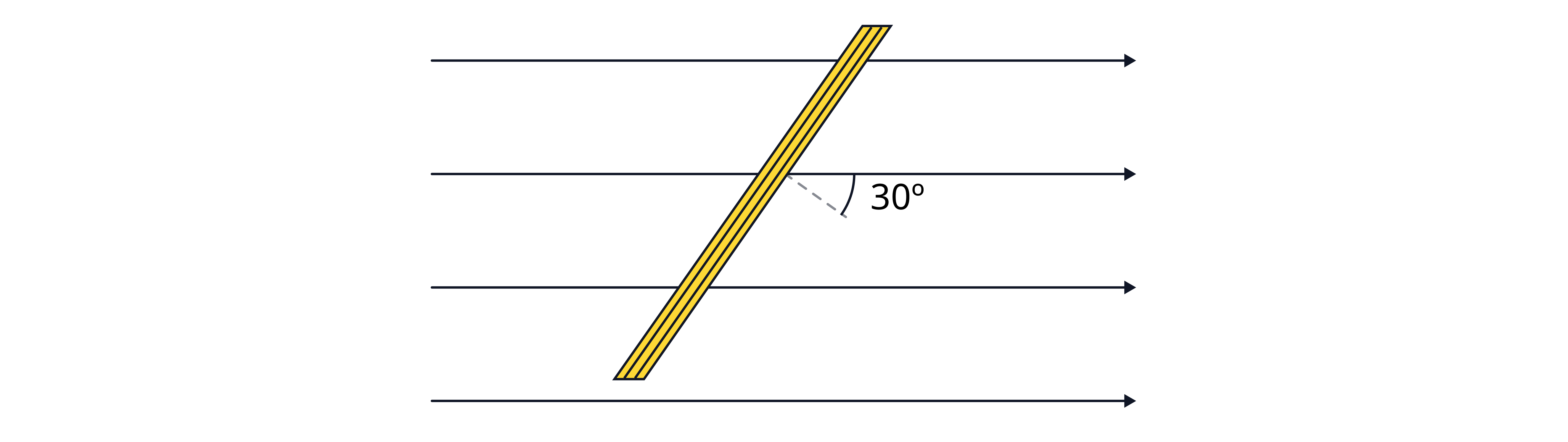
The diagram below shows a coil in a magnetic field. The normal to the plane of the coil is below the magnetic field lines as shown. The magnetic flux density is and the area of the coil is.
The maximum flux linkage of the coil while rotating is turns.
Calculate the number of turns in the coil
Calculate the flux linkage at the instant shown.
The coil rotates in the magnetic field with a period of 0.25 seconds. Calculate the peak electromotive force (emf) in the coil.
-> Check out Brook's video explanation for more help.
Answer: