Circuits
Brook Edgar
Teacher

Explainer Video
Ohmic and Non-Ohmic Conductors
Current is defined as the rate of flow of charge.
Potential difference (pd) is the energy transferred per unit charge across a component / between two points in a circuit.
Electromotive force () is the energy transferred per unit charge by the source to move one unit charge around the circuit.
Ohm’s law states that the pd across a metallic conductor is directly proportional to the current through it, provided the physical conditions do not change (e.g. temperature), leading to the equation .
We can prove that the graph below shows that pd and current are directly proportional by showing that = a constant for at least three different data points.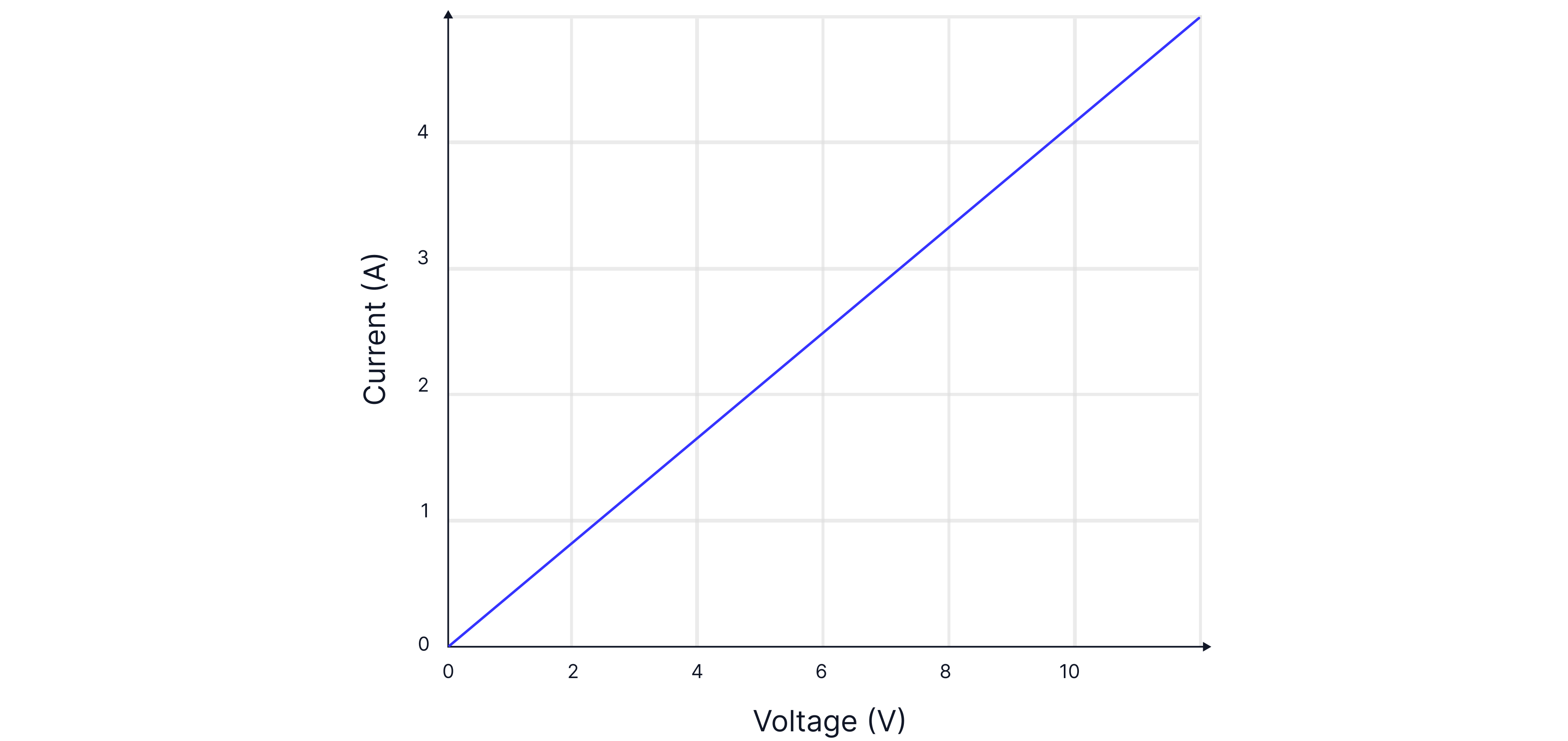
Therefore, is a constant, . This graph is that for an ohmic conductor with resistance two ohms.
Diode

The graph below is for a diode.
A diode is not an ohmic conductor as it ensures that current can only flow in one direction.

Worked Example
Design a method to produce an I-V graph for a filament bulb.
Answer:
Step : Set up your circuit by connecting a bulb in series with an ammeter, a variable resistor, and a cell. Connect a voltmeter across the bulb.
Step : Using the variable resistor, record at least 10 different readings of current and potential difference.
Step : Change the polarity of the cell and repeat.
Step : Plot a graph of potential difference against current.

Teacher Tips: The voltmeter should be placed across the component to measure its potential difference. Ideally, the voltmeter has infinite resistance. A variable resistor is needed to obtain more than one value for current and potential difference, as it allows you to adjust the potential difference across the component being tested.
A bulb is a non-ohmic conductor. As the current increases, the temperature of the wire increases, causing more collisions between the free-moving electrons and the metal ions. This increases the resistance. Therefore, the I-V graph is not a straight line through the origin.
Resistor Rules:
When components are in series the total resistance is given by:

The total resistance of circuit A is .
We can now calculate the total current in the circuit,
When components are in parallel the total resistance is given by:

The total resistance of circuit B is:
The current in circuit B is therefore, .
Worked Example
How many electrons are there in .
Answer:
Teacher Tips: The relative charge of an electron is - but its actual charge is -.
Worked Example
The potential difference across a resistor is . How much work is done if of charge flows in seconds?
Hence, calculate the power lost across the resistor.
Answer:
Worked Example
Calculate the total current leaving the cell and the current through the resistor.

Answer:
First, we need to calculate the total resistance of the circuit by finding the total resistance of the two resistors in parallel and then treating this as a single resistor in series with the other.
To calculate the current through the resistor, , we need to know the pd across it. First, we will find the pd across the resistor and subtract this from the pd of the cell to find the pd across the two parallel resistors.
Across resistor
Across
Remember: It is good to memorise some equations as you use them often and in definitions. Such as, .
Semiconductors
A positive temperature coefficient means that as the temperature increases the resistance increases. This is the case for conventional conductors. However, for semiconductors, as the temperature increases the resistance decreases. They have a negative temperature coefficient.
In metals, as the temperature is increased, the metal ions vibrate with an increased amplitude, and there are more collisions with moving electrons, which causes resistance to increase.
In a thermistor, the metal is a semiconductor. As the temperature increases, more valence electrons move into the conduction band, resulting in a greater electron density. The current increases as the resistance decreases.

Electrons in the conduction band are free to move. Electrons in the valence band are bound to the atom.

Metals are always conductors because all their free electrons are in the conduction band. The electrons are free to move through the structure.
In semiconductors, if more energy is supplied by, for example, increasing the temperature, the electrons can gain enough energy to move from the valence band to the conduction band. This means that the electrons are now free to move and carry charge. Therefore, semiconductors like silicon become more conductive at higher temperatures.
Insulators do not have any electrons in the conduction band. It is very unlikely for electrons in insulators to move to the conduction band because the gap between the valence band and conduction band is so large. A significant amount of energy would be required to overcome this energy gap.

LDR
In an LDR, as the light intensity increases, the resistance decreases. This is because more electrons have moved from the valence band to the conduction band by absorbing energy from the light.
The blue line in the graph represents a lower light intensity as it has a higher resistance at any point than the red line, .
Practice Questions
Three identical filament lamps, P, Q, R are connected. The filament in Q melts so it no longer conducts. Explain why lamp P becomes brighter and lamp R dimmer.

-> Check out Brook's video explanation for more help.
Answer:
R is dimmer as the resistance of the whole circuit increases, so the total current decreases. The resistance of R is fixed, as , there is less power as there is less current through it.
P is brighter as the potential difference across P increased, as the potential difference across R decreased. so, as the pd across P is greater and its resistance remains fixed, the power is greater and thus the bulb is brighter.
The graph shows the current-voltage (I-V) characteristics for a resistor and a filament lamp.

Explain why the graph for the filament lamp is a curve.
-> Check out Brook's video explanation for more help.
Answer:
As current increases, temperature increases. The metal ions vibrate more, resulting in more collisions between the electrons and the metal ions, which causes an increase in resistance. So at higher currents ( and hence higher temperature), the ratio of pd to current increases.
Calculate the potential difference across the resistor.

-> Check out Brook's video explanation for more help.
Answer:
Potential difference =