Potential divider
Brook Edgar
Teacher

Explainer Video
Potential Dividers
Potential Dividers are used to split the voltage from the power supply into smaller parts. They can be used to vary the brightness of a bulb or LED, or used as sensors, for example, a thermistor in a potential divider can vary the pd depending on the temperature.
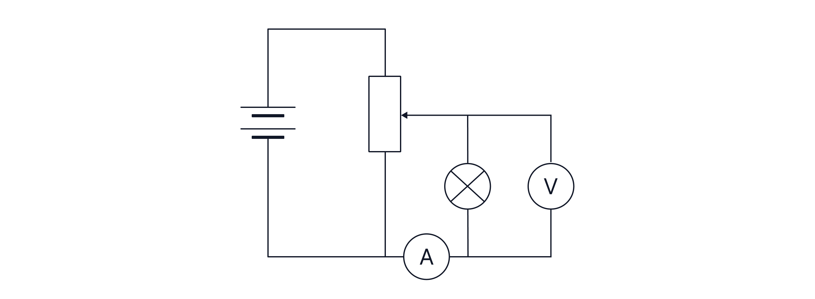
The diagram shows a potential divider.

As the temperature increases, the resistance of the NTC thermistor will decrease. The total resistance of the circuit will therefore decrease. It will be easier for the electrons to pass through the thermistor, requiring less energy to be transferred per unit charge. Consequently, the potential difference (pd) across the thermistor will decrease, and thus the voltmeter reading will be lower.
To have a heater turn on when it gets too cold, replace the voltmeter with a heater. As the temperature of the room decreases on a cold day, the resistance thermistors resistance increases. The thermistor and heater would receive more voltage and hence more power, causing the heater to turn on.
Worked Example
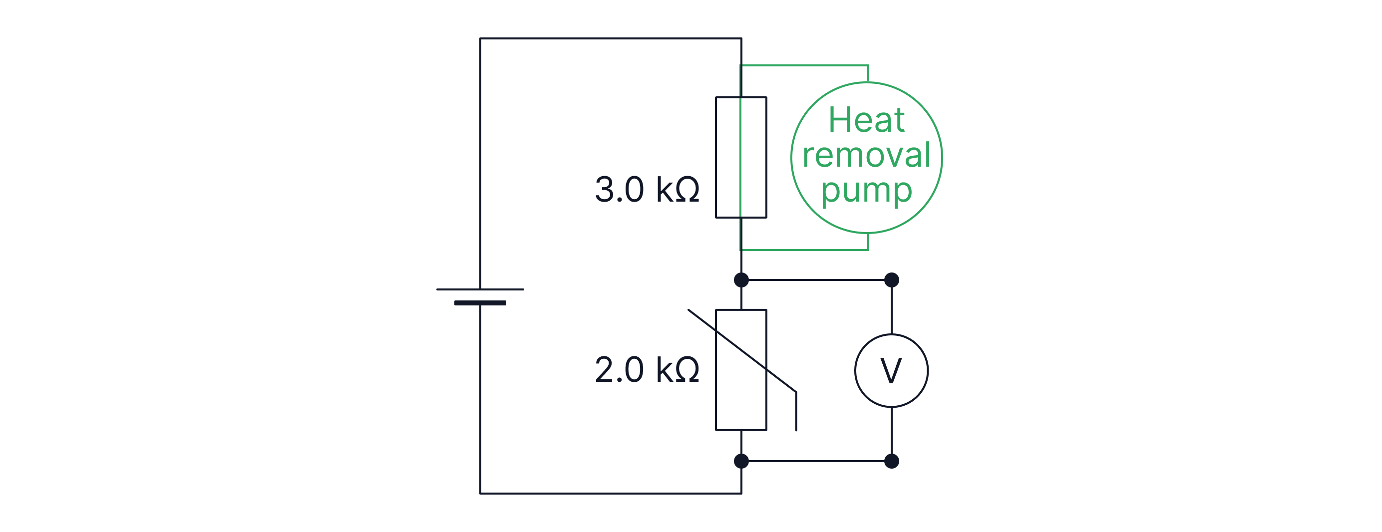
Draw a circuit for a heat removal pump in a fridge.
Answer:
You want the heat removal pump to turn on when the temperature is too high.
When the temperature is high, the resistance of the thermistor is low. As a result, an electron/unit charge will lose almost no energy when passing through the thermistor, but it needs to lose all of its energy before it can return to the cell. Therefore, it will lose a lot of energy trying to go through the fixed resistor. We connect the heat removal pump across the fixed resistor to transfer a significant amount of energy here.
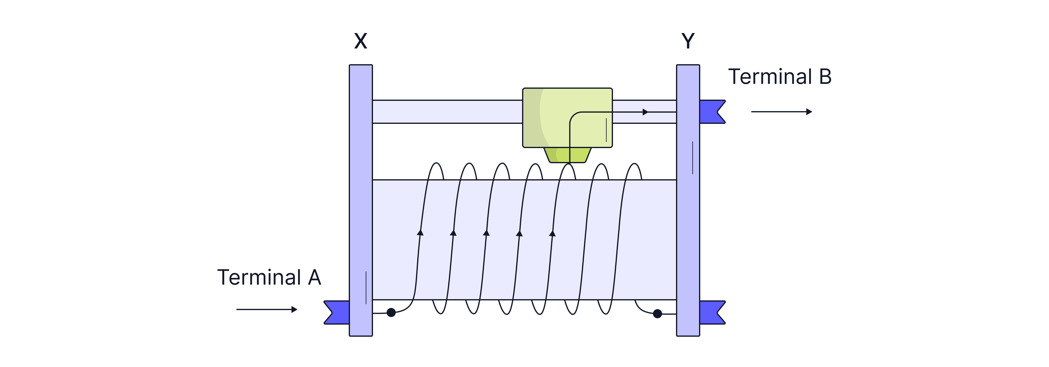
A rheostat can be used as a variable resistor. At position Y, the resistance between terminals A and B is the highest, as this is when the wire is at its longest. As resistance is proportional to the length of the wire, the longer the wire, the larger the resistance. Therefore, at position X, the resistance between terminals A and B is at its lowest.
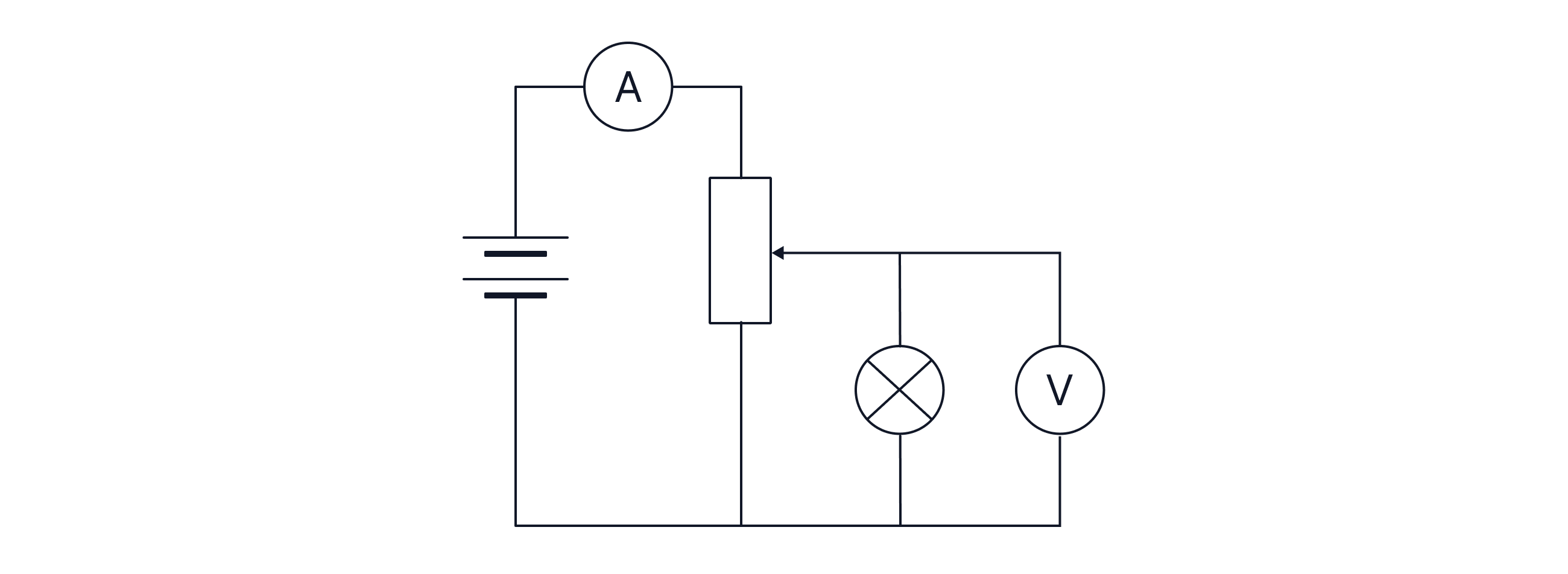
The circuit diagram below shows a rheostat used to vary the pd across the bulb. Maximum current flows when the sliding contact is moved all the way to the left, minimising the length of the wire the current flows through in the rheostat and thus lowering resistance.

The resistance of the rheostat is effectively zero now, as it has been 'skipped' -> no current flows through it. The only resistance now is due to the bulb in the circuit, so the maximum current can be found:
For minimum current, and thus a dimmer bulb, we move the sliding contact all the way to the right -> the longer the wire, the higher the resistance. The rheostat now has a maximum resistance of 16 ohms. The total resistance of the circuit is now the sum of the resistance in the rheostat and the bulb, as the two components are connected in series.
Short Circuit
A short circuit provides a path of minimal resistance to bypass a component. You can short circuit a component by connecting a wire across it which has effectively zero resistance. See below:
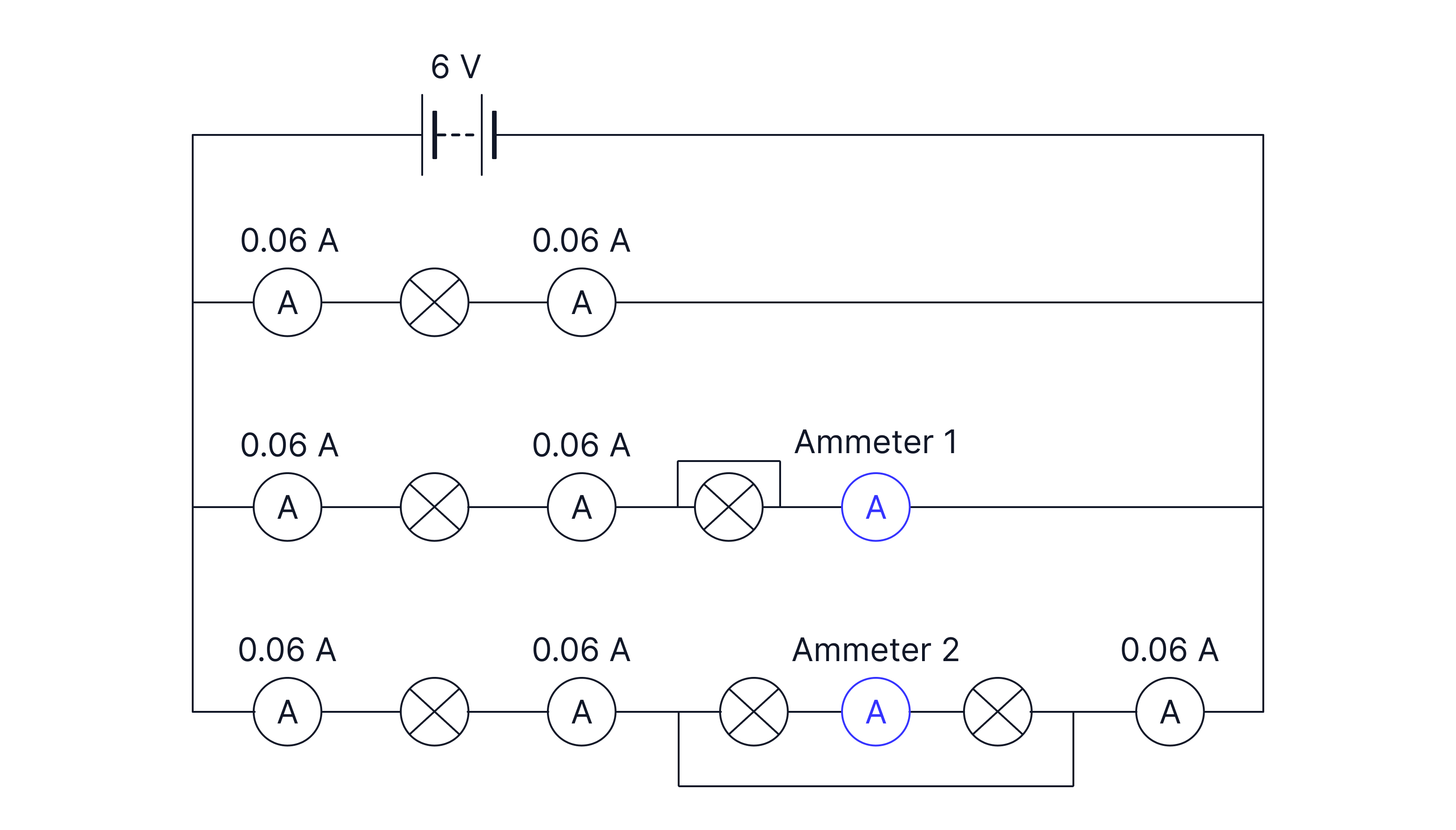
In the circuit diagram above, ammeter one will read as the bulb is short-circuited, and current is conserved. However, ammeter two will read as all the current will take the alternative path of least resistance. We have short-circuited the two bulbs and the ammeter here.
Worked Example
Which of the circuits below is the best for exploring the I-V characteristics of the resistor?
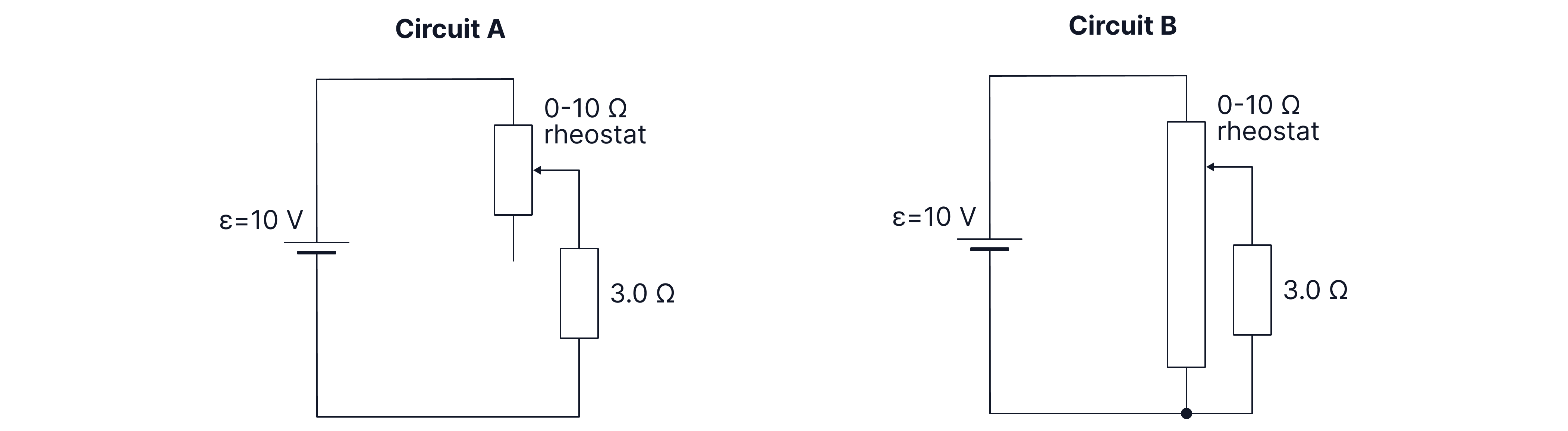
Answer:
We want the circuit which gives us a wider range of currents through the resistor. We then have to find the maximum and minimum current flowing through the resistor in each circuit.
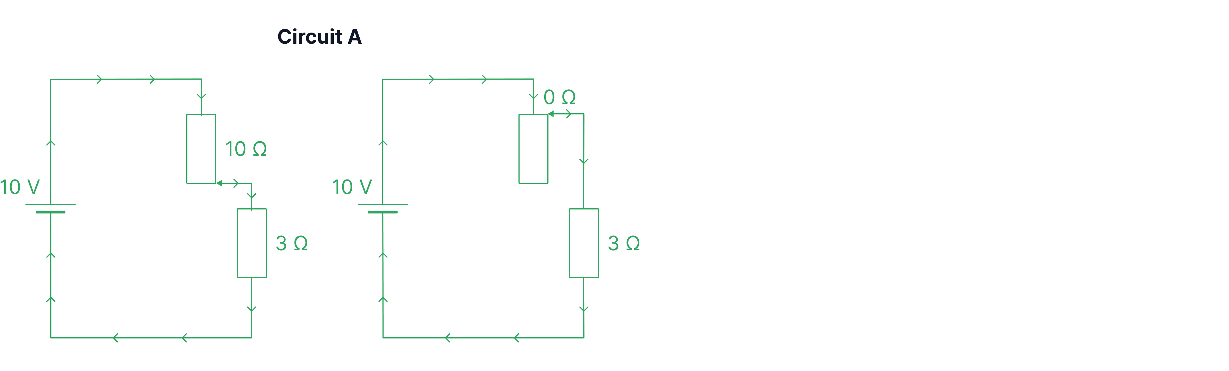
For each circuit, we will draw out the two extremes. The set-ups that have the highest and lowest resistance.
For circuit A, we can connect the rheostat at the bottom end for maximum resistance and at the top end for the least resistance.
For circuit B we can connect the resistor across the length of the rheostat at the top or connect it at the bottom, thus short circuiting the resistor.
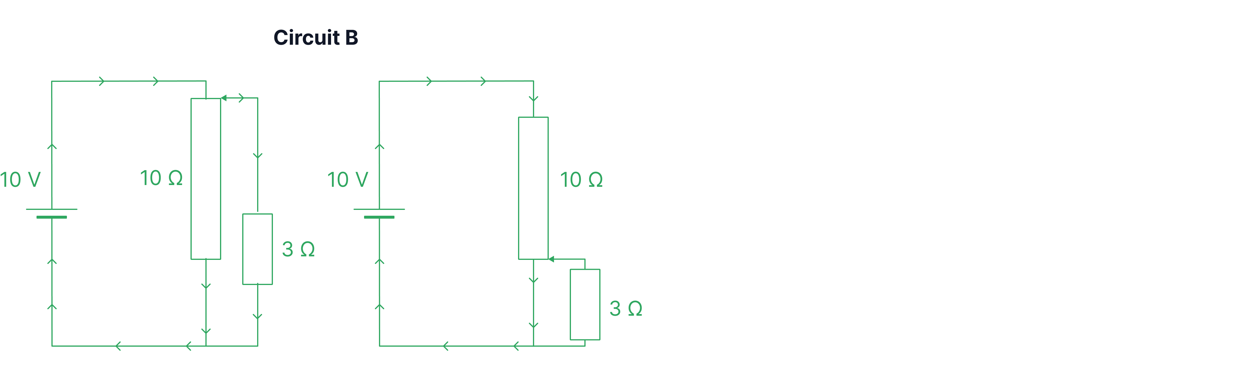
Circuit B is the best choice as it gives us a wider range of data points, which is better when plotting a graph. In circuit B, the current has a range of , whereas circuit A has a range of .
Practice Questions
Calculate the resistance of the thermistor in the circuit below.
If the temperature is increased, what happens to the reading on the voltmeter?
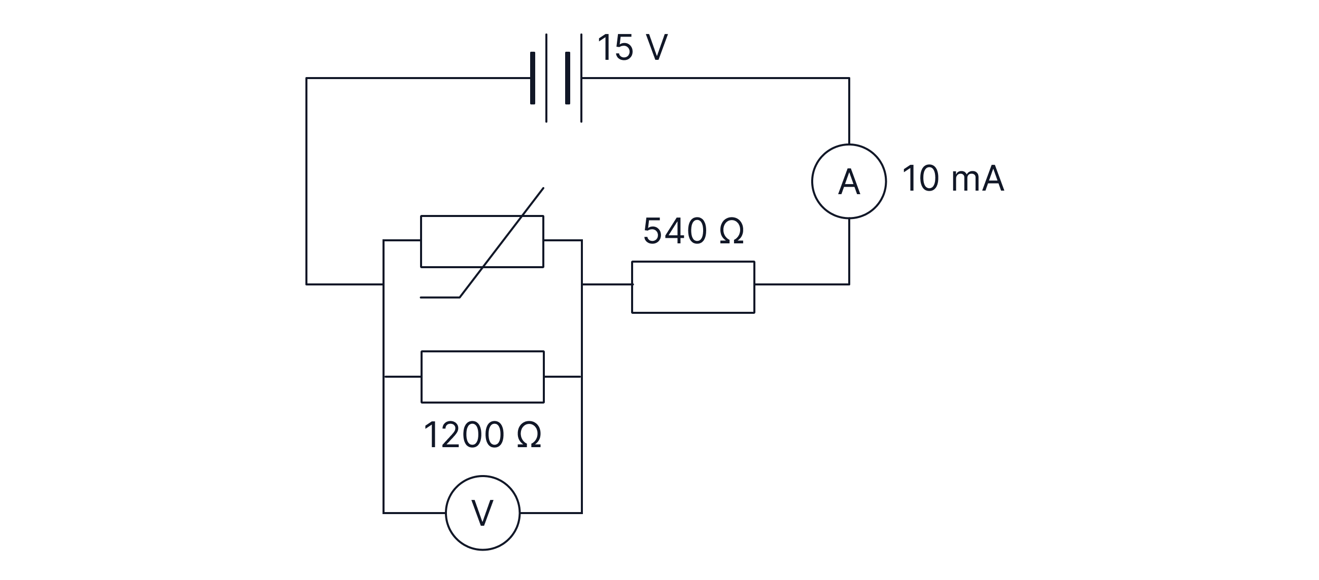
-> Check out Brook's video explanation for more help.
Answer:
The reading on the voltmeter will decrease.
A battery has an emf of and negligible internal resistance.
Which circuit below allows us to measure the pd and current of the bulb for the largest possible range of values.


-> Check out Brook's video explanation for more help.
Answer: