Young's Double Slit Experiment
Brook Edgar
Teacher

Explainer Video
Introduction to the Double Slit Experiment
We know that light is a wave as it diffracts. Diffraction is the bending or spreading out of waves around obstacles/gaps
Maximum diffraction occurs when the size of the obstacle/gap is the same order of magnitude as the wavelength of the wave.
For example, sound waves can diffract around a door, but light can't, as light has a much smaller wavelength. This is why we can hear someone from the other room, but we cannot see them.

Young's double slit experiment shows us the wave properties of light as the waves diffract from the two slits and superpose when they meet. If directed at a screen, an interference pattern of alternate dark and bright fringes can be seen.
The interference pattern can only be observed if the light waves are coherent. This means that the waves emerging from the slits have the same frequency/wavelength and have a constant phase difference. To achieve this, a laser beam is used instead of a bulb or candle as it provides monochromatic light (light of a single colour/wavelength).
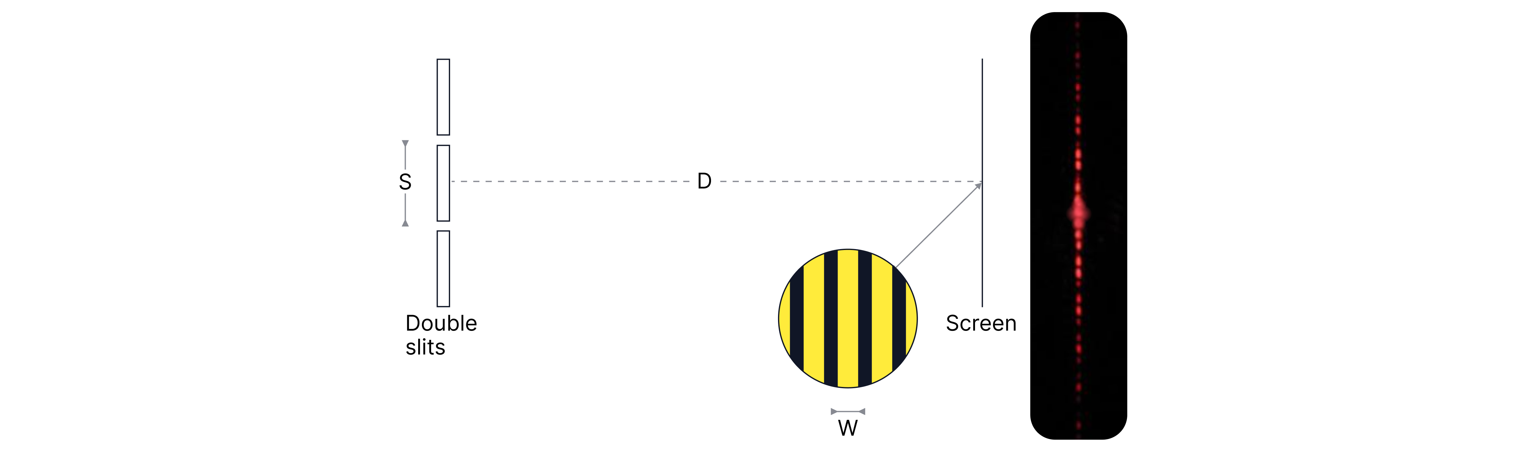
If the two waves are exactly in phase, a central maximum is visible on the screen, where constructive interference occurs because the path difference of the waves is zero.
Formula:
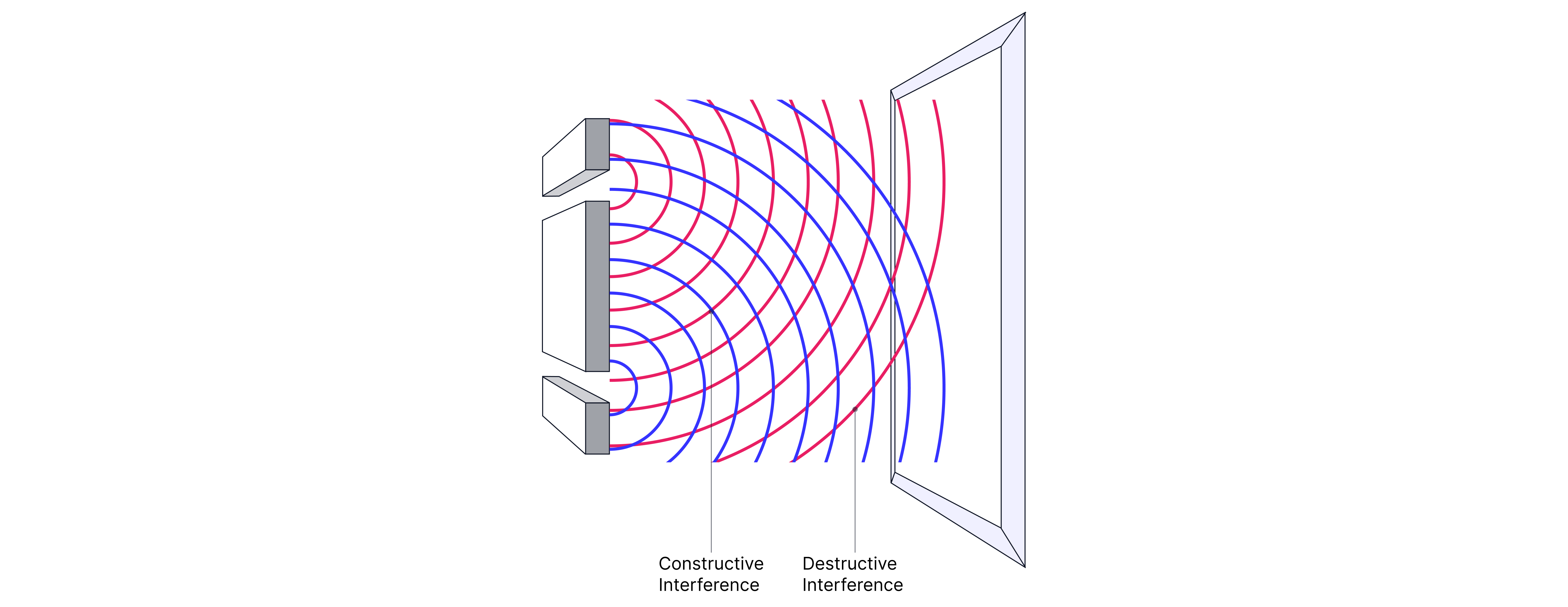
Constructive interference, forming a bright fringe occurs if the path difference between the two waves is or , where is an integer and the waves meet exactly in phase, . This would occur for example if the two waves both arrive at a peak.

If the path difference is then we get destructive interference. A dark fringe is formed as the two waves are in antiphase, . This would occur for example if one wave arrives as a peak and the other as a trough.

To summarise: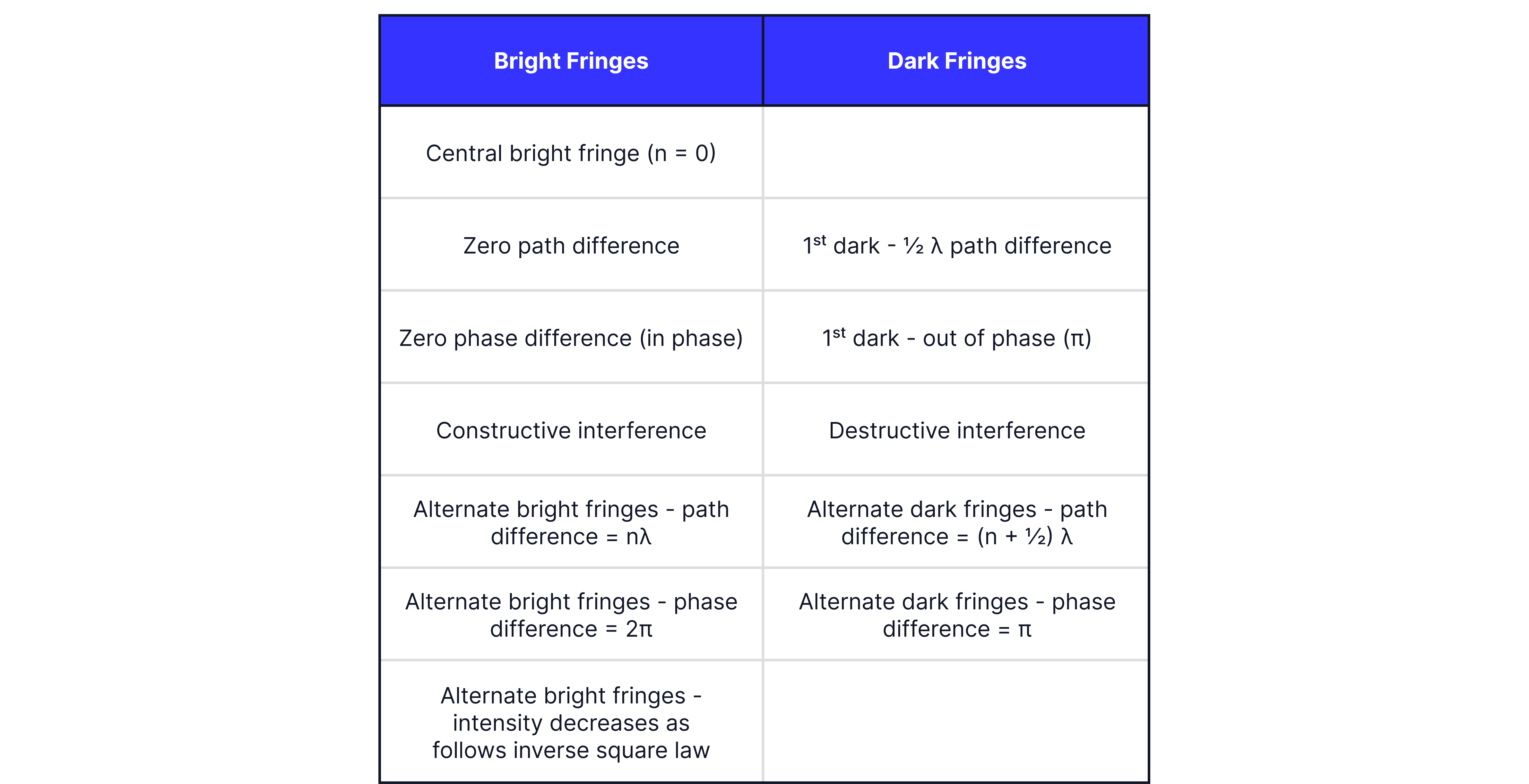
Practical Observations
If slit separation, , is increased then fringe spacing, , will decrease as seen from the equation, as they are inversely proportional. The fringes will be closer together and thus harder to measure, which is why a smaller slit separation is ideal.
If violet light is used instead of red light, the fringes will become much closer together, as violet light has a shorter wavelength than red light. This is because wavelength is directly proportional to fringe separation.
If we increased the distance between the slits and the screen, the fringe pattern would widen. In practice, this is the usual adjustment to make, as when measuring fringe spacing, we want the fringes to be as far apart as possible and to measure across multiple fringes to reduce the percentage uncertainty in our results. In practice, you would measure the distance across multiple fringes using a vernier calliper, as they have better resolution than a ruler.
Worked Example
Explain how:
Bright fringes are formed.
Dark fringes are formed.
Answer:
When the path difference of the waves arriving from the slits is ( is an integer), and they are exactly in phase , the waves superpose, constructive interference occurs and a bright fringe is observed.
When the path difference of the waves arriving from the slits is , and they are in antiphase , the waves superpose, destructive interference occurs and a dark fringe is observed.
Worked Example

In the diagram above, determine the type of fringe formed at point . The wavelength of each wave is .
Answer:
The wave from slit two travels further than the wave from slit one.
The waves have a path difference of .
Waves will meet in antiphase and therefore, P is a dark fringe.
Worked Example
A laser emits light of wavelength at a double slit which has a slit separation of . The interference fringes are observed from the slits. Calculate the fringe separation.
Answer:
Practice Questions

and emit sound at the same frequency. As a detector is moved from to , maximum sound intensity is heard at and and consecutive minima at and . State which below represents the wavelength of the sound.
-> Check out Brook's video explanation for more help.
Answer: